Hardware
This section contains information specific to different hardware products and accessories. This includes information on modules and actuators, mechanical and electical accessories, robot kits, and details of any hardware-specific parameters for the APIs.
| CAD files of the actuators and accessories are available at cad.hebi.us. |
Modules
HEBI modules are ethernet-enabled devices that serve as building blocks for a robot or automated system. These modules include actuators to provide physical motion, and devices to interface with other sensors and I/O. Modules run firmware that allow them to communicate over a standard ethernet connection. Aspects of the firmware that are common to all modules are documented in Core Concepts, while aspects that are module-specific are documented below.
T-Series & R-Series Actuators
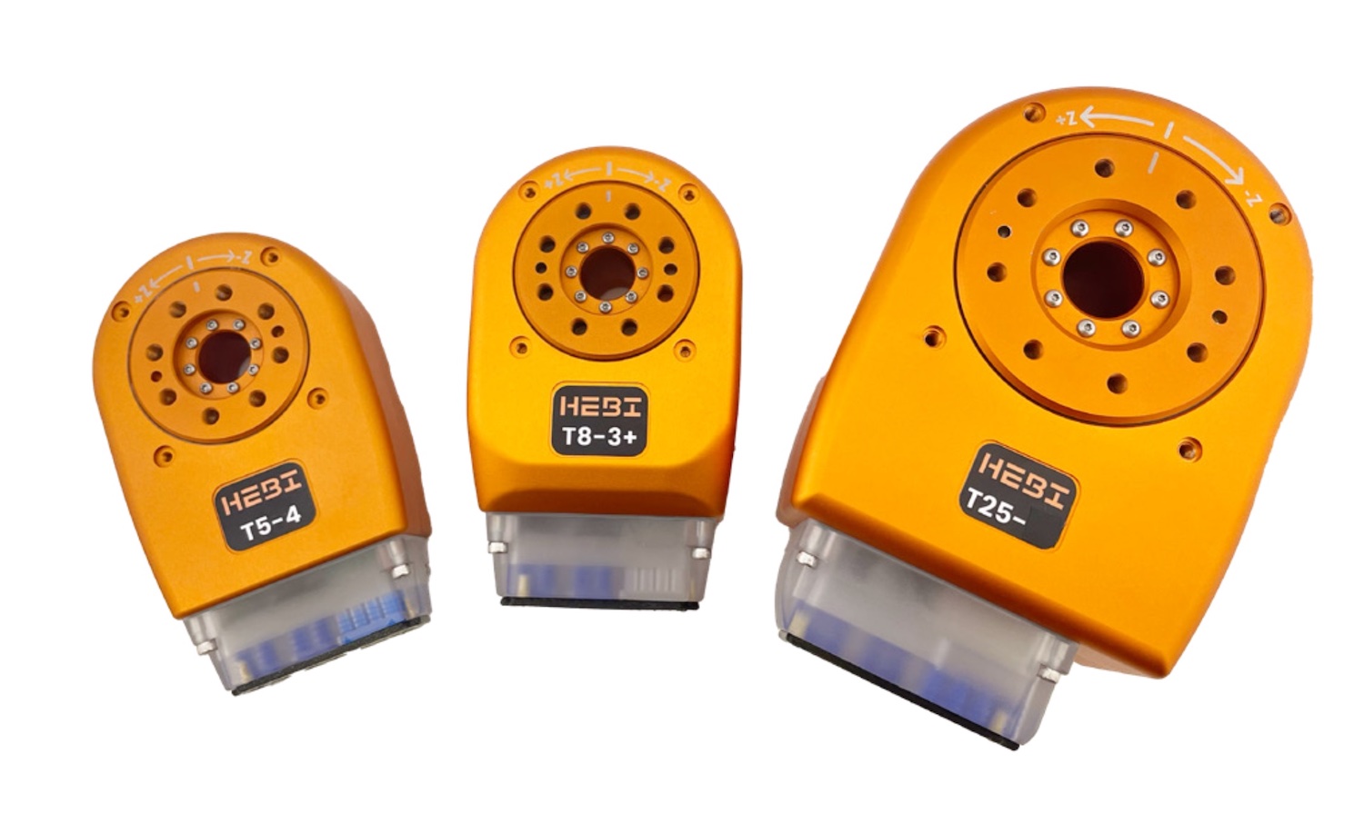
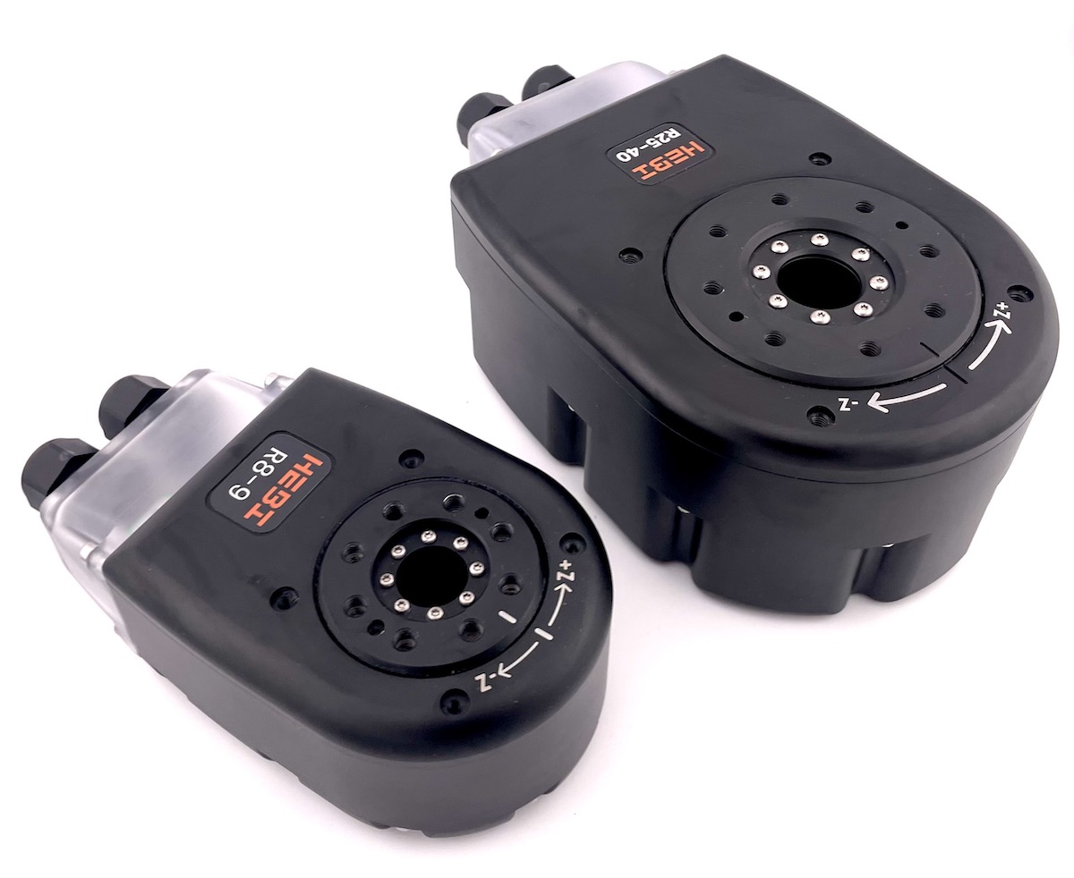
The T-Series and R-Series Actuators are 'smart' series-elastic actuators that integrate a brushless motor, geartrain, spring, encoders, and control electronics into a compact package that run on standard DC voltages and communicate using standard 10/100Mbps Ethernet over plastic optical fiber (POF). These actuators are designed to function as full-featured robotic components and enable the simultaneous control of position, velocity, and torque. Each actuator also has a wide range of other sensors, all of which can be easily accessed in the the various APIs. The T-Series Actuators are great for everyday robotics research and indoor robotics systems whereas, the R-Series Actuators are sealed to IP67 that allows them to be used in challenging field applications.
| The X-Series section has been removed. The charts and information below for the T5 and T8 Actuators can be directly correlated to the corresponding X-Series Actuators. |
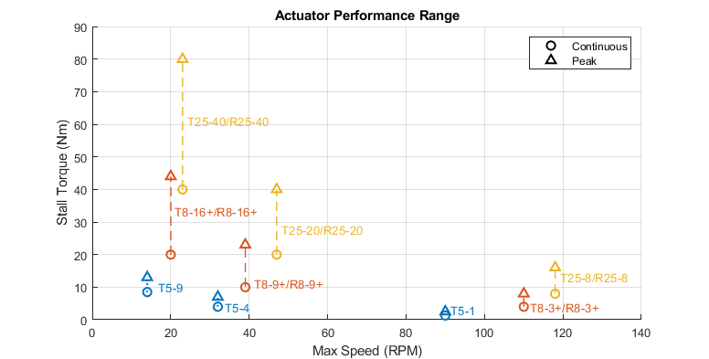
Maximum Performance Range
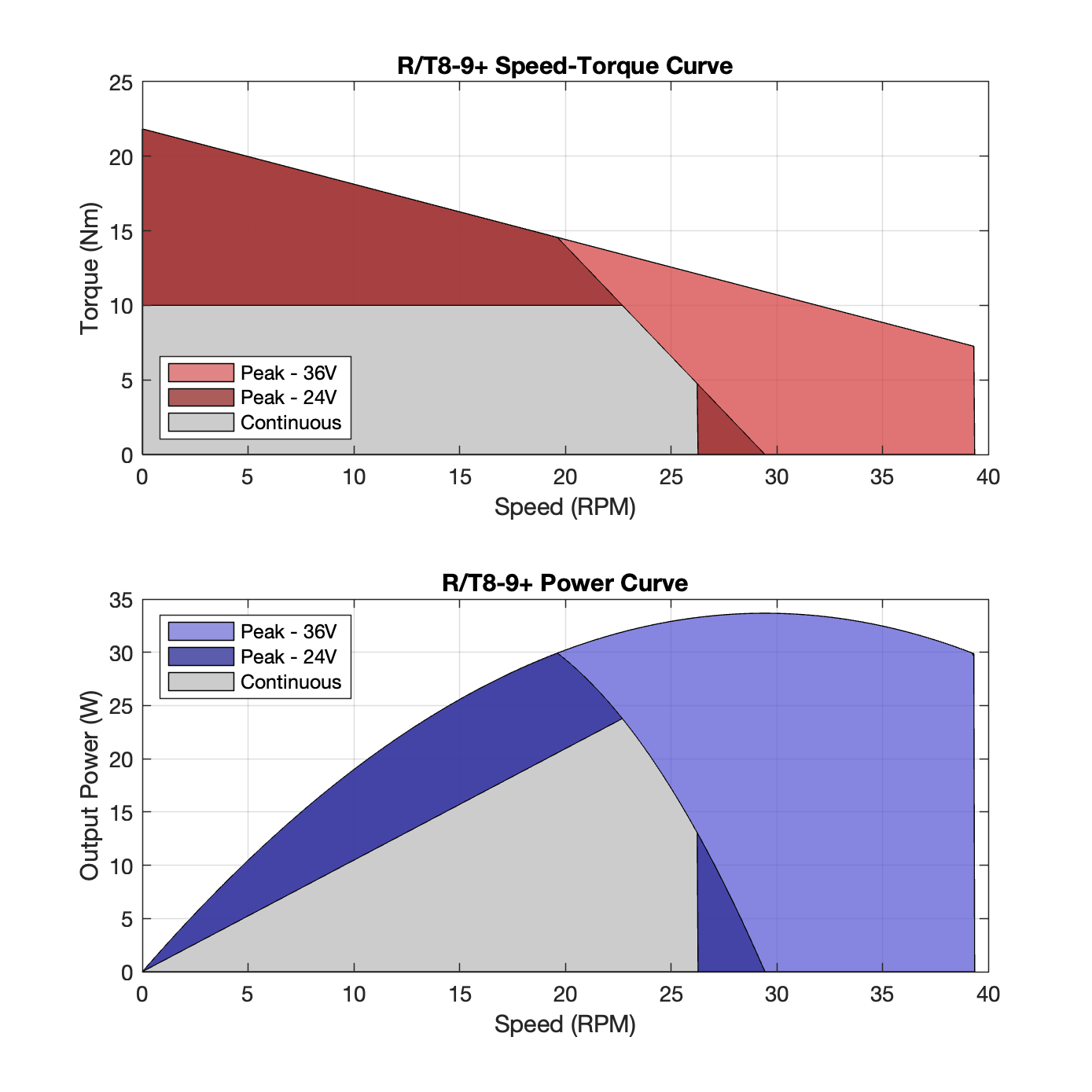
The chart below indicates, separately, the maximum no-load speed and stall torque capabilities of the different models of T-Series and R-Series actuators.
For example, an R8-9 is not capable of continuously providing 9 Nm of torque at 30 RPM. It is capable of a continuously spinning at maximum speed of 30 RPM at a lower torque, and it is capable of exerting 9 Nm of torque at a lower speed.
More detailed performance information for each actuator is provided in the additional sections below.
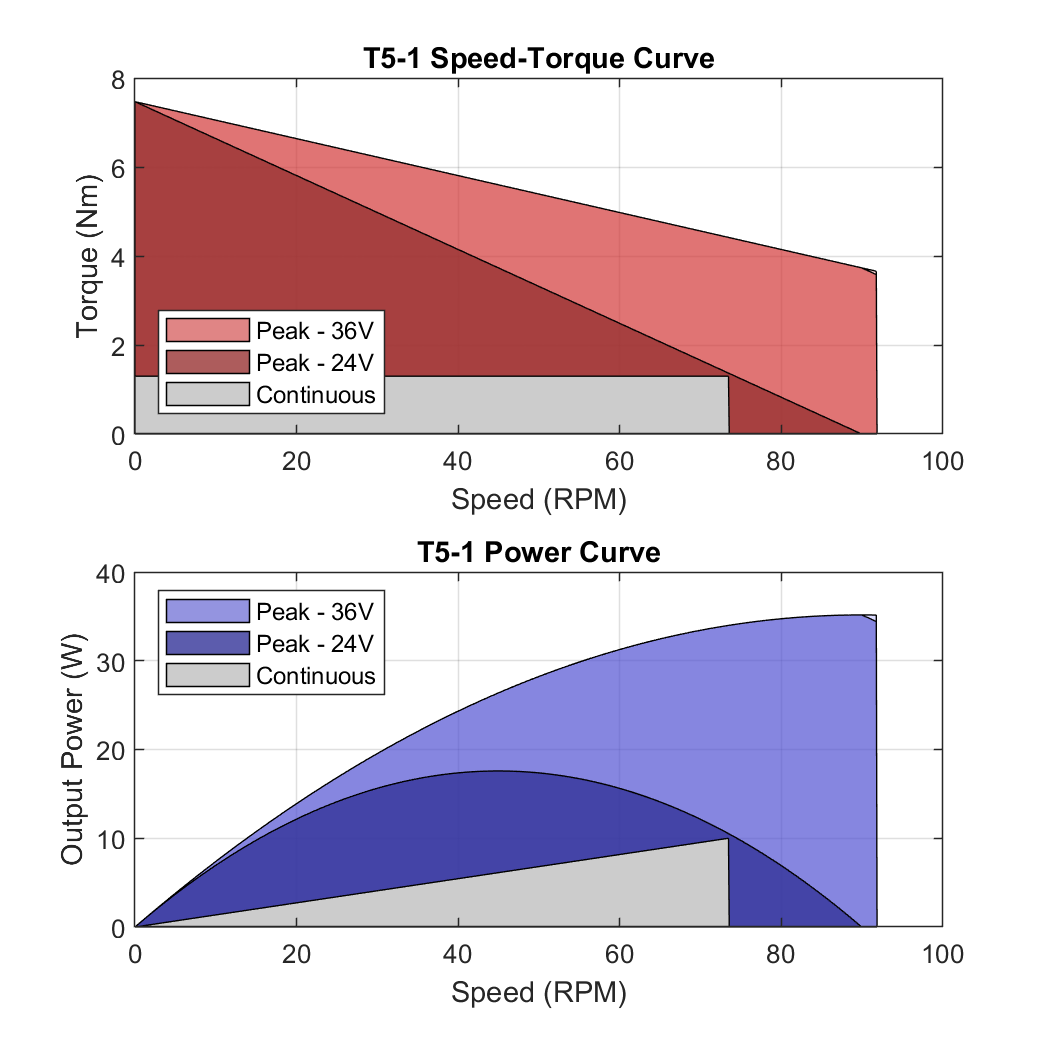
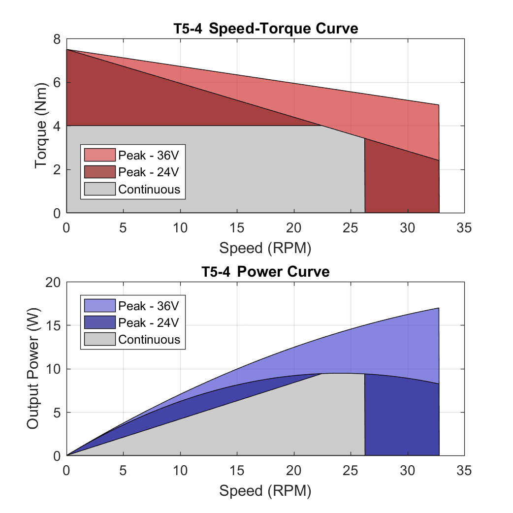
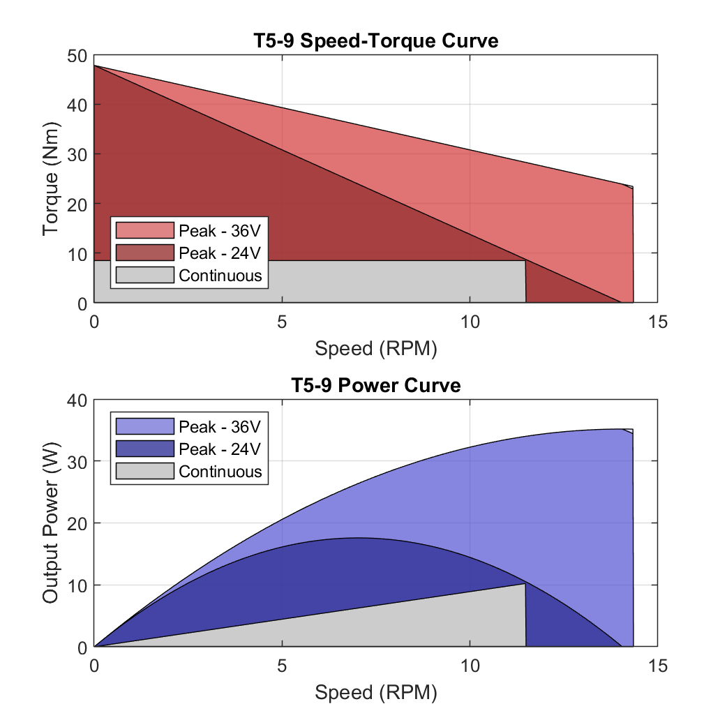
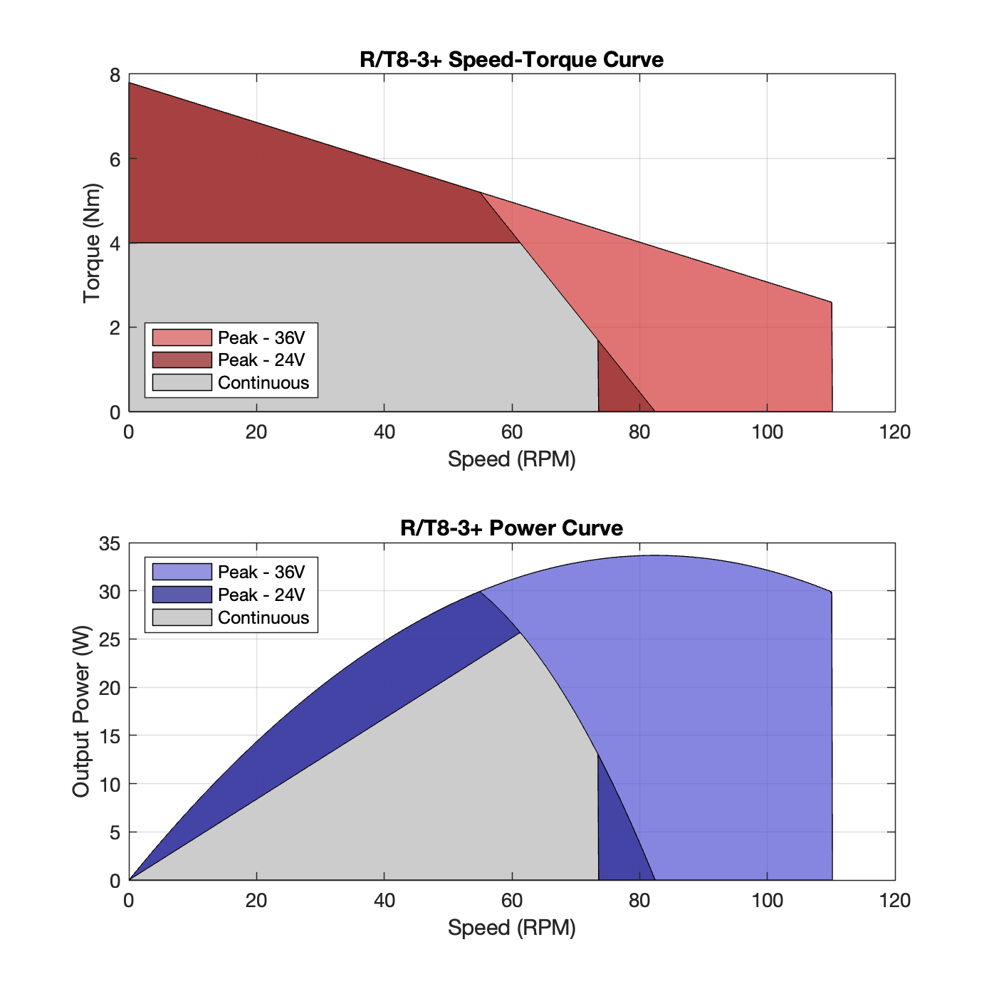
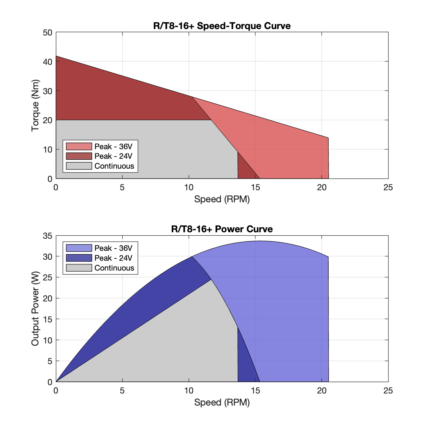
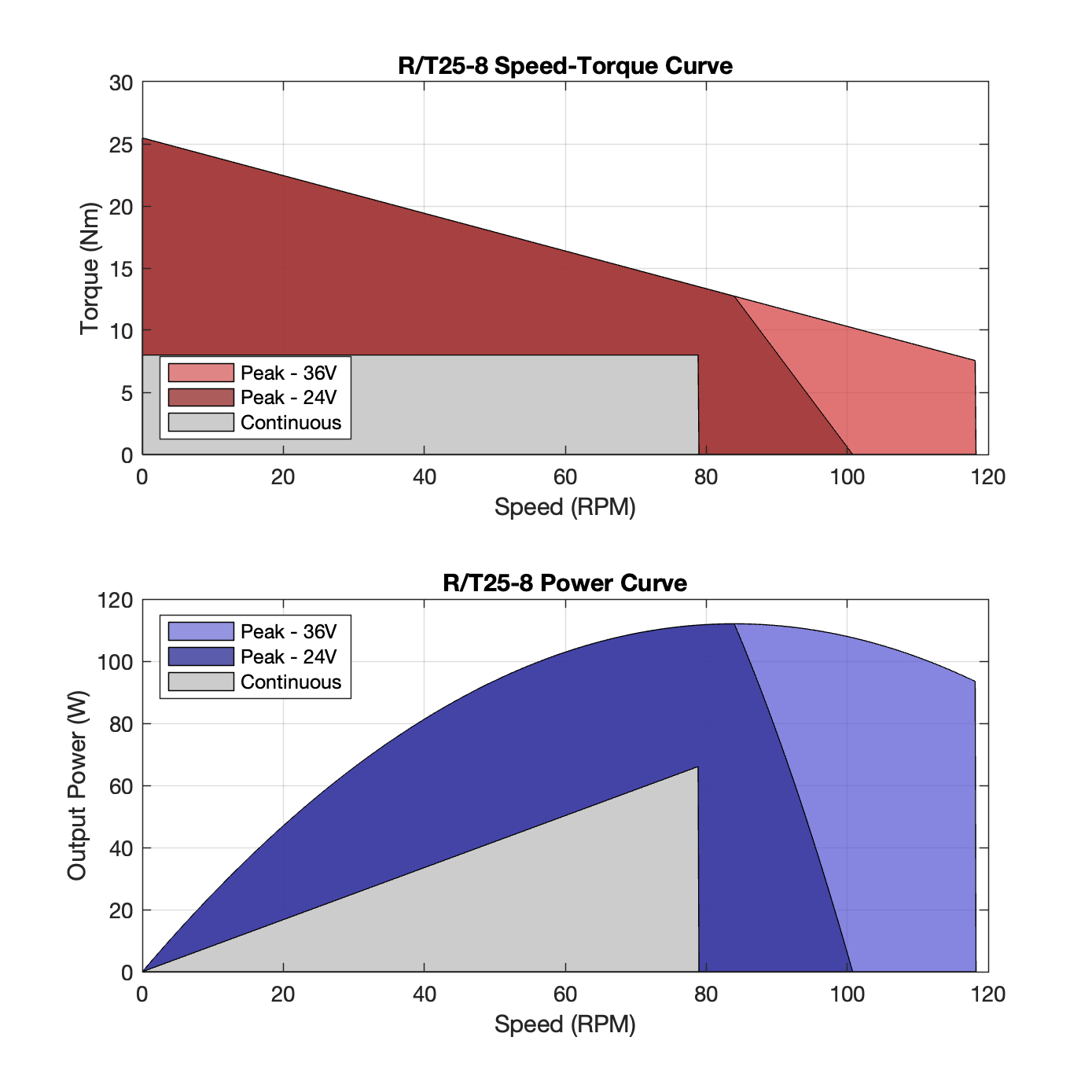
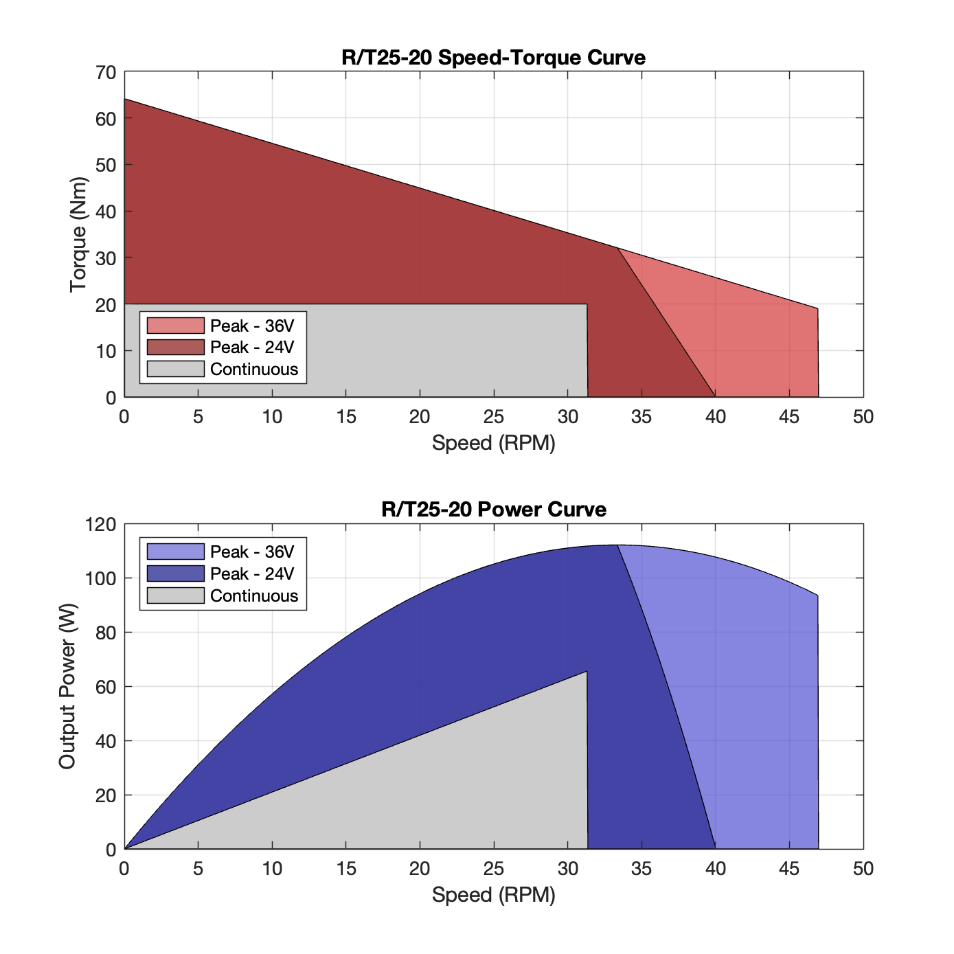
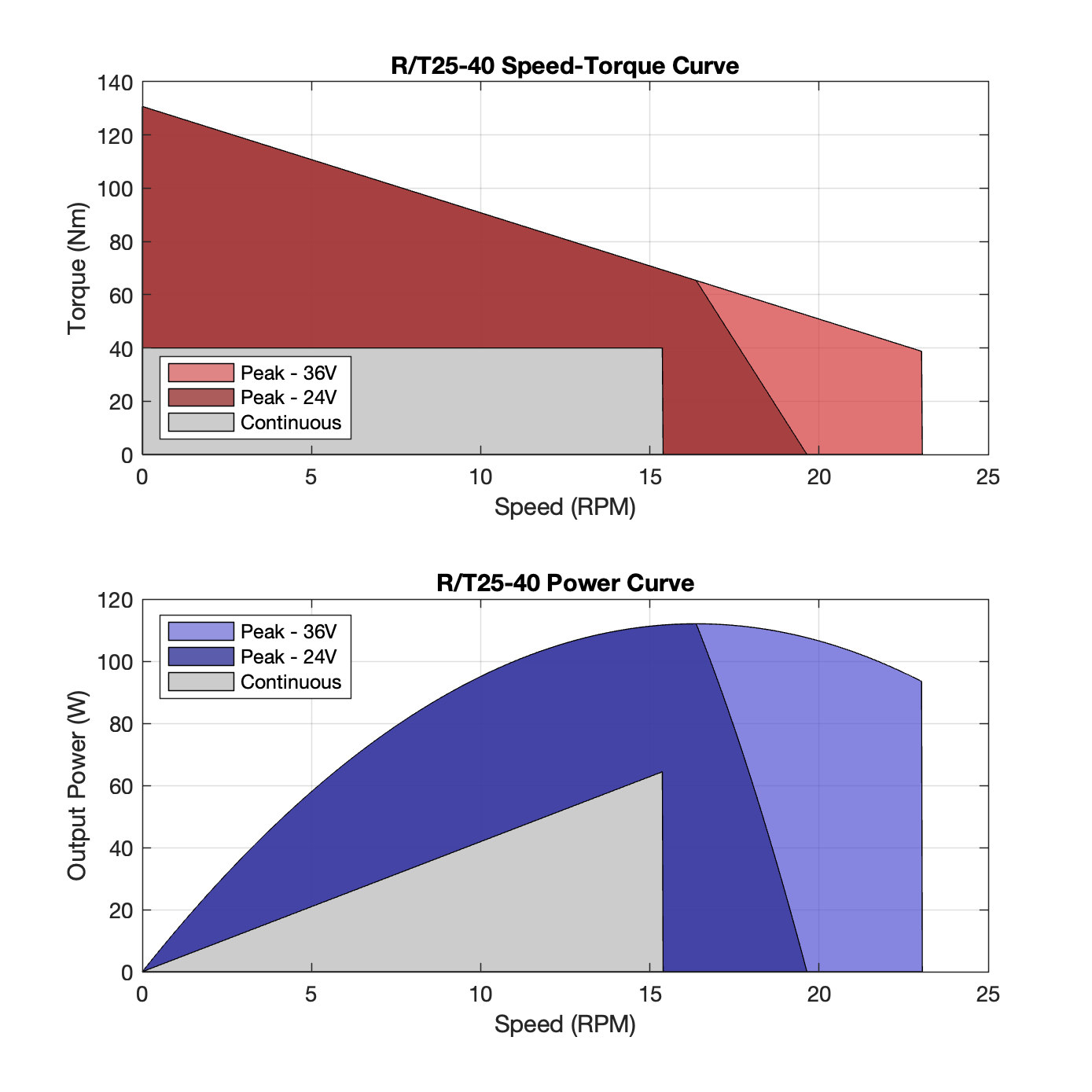
Speed-Torque Curves
Each actuator has a range where it can perform continuously, as well as a peak range where it can perform intermittently. While T-Series and R-Series actuators are rated running at 24V, they are capable of increased intermittent output at higher voltages.
The speed-torque curves below show both the continuous and intermittent operating ranges at 24V, as well as 36V and above. While the actuators can be run at bus voltages up to 48V, the performance is limited in firmware to the equivalent to 36V, allowing safe operation while decreasing the amount of current drawn at the power bus. The ranges shown below are approximate and assume an actuator in normal room-temperature conditions without additional cooling.
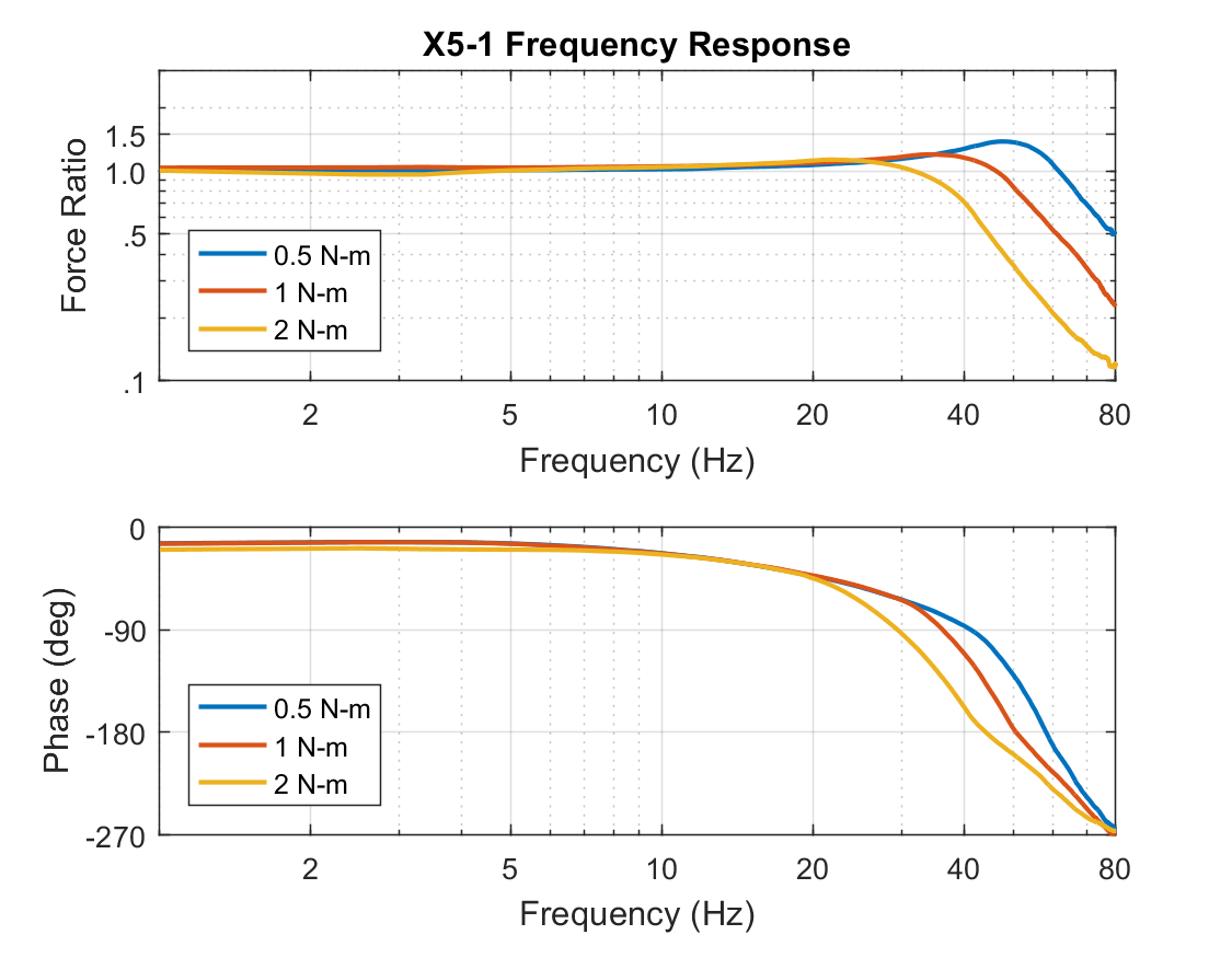
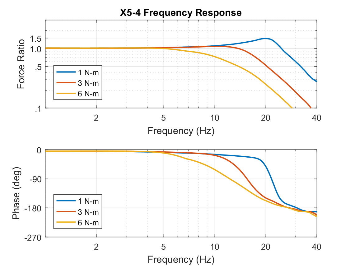
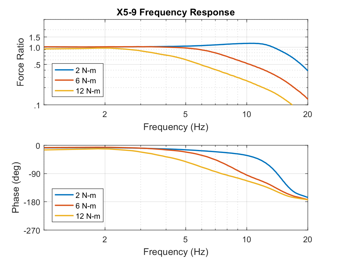
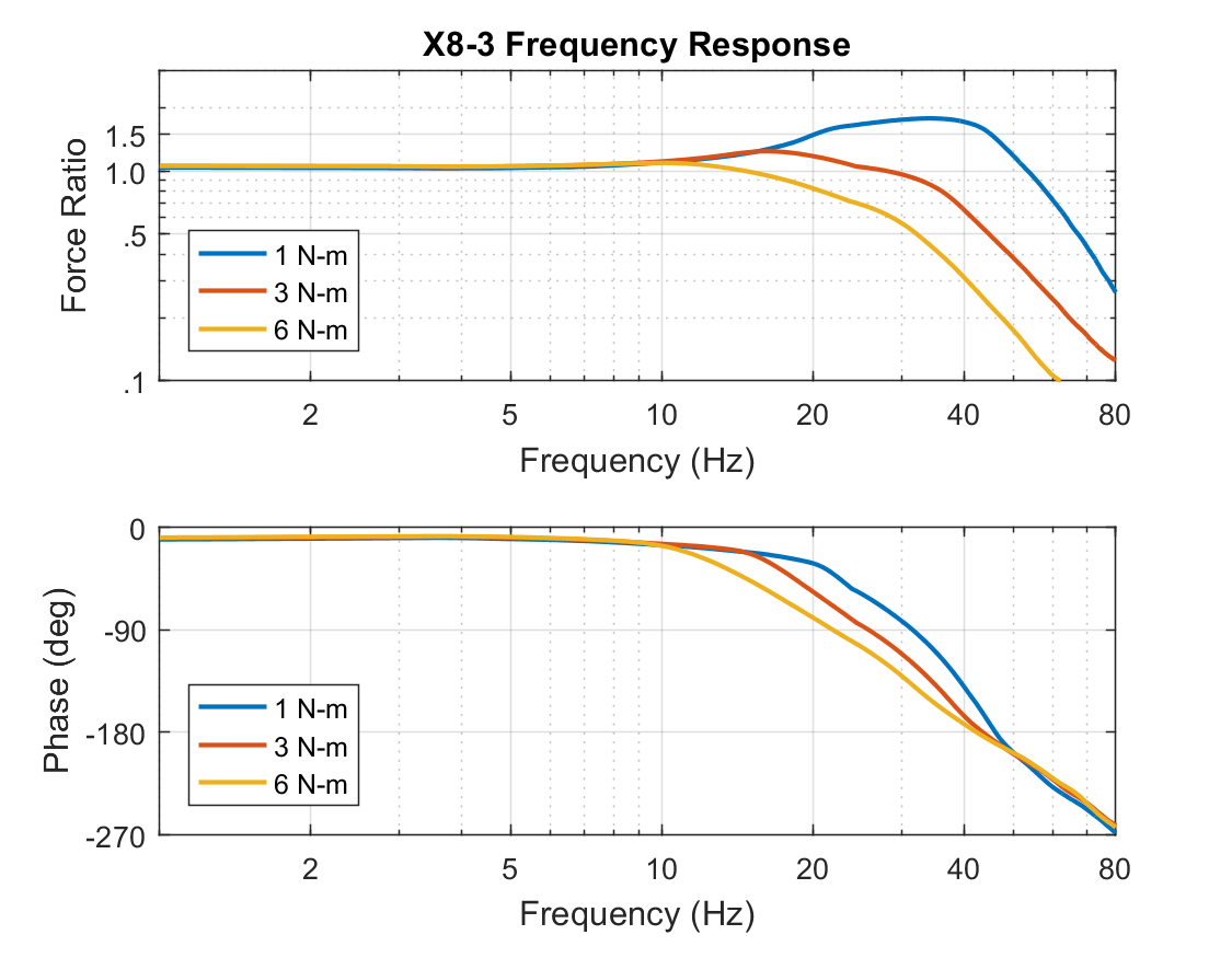
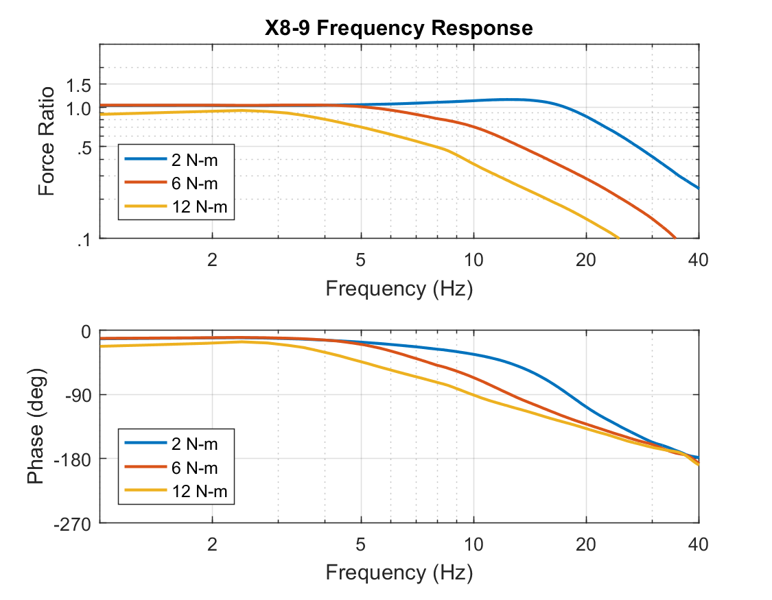
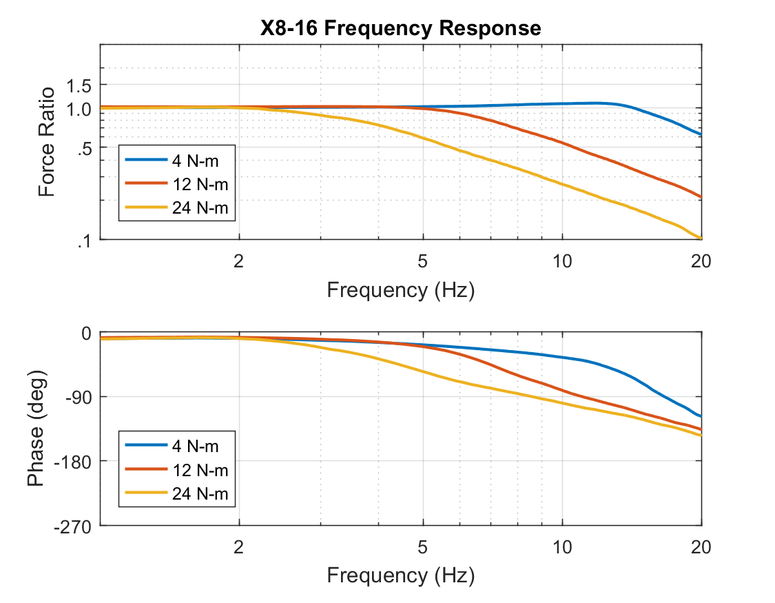
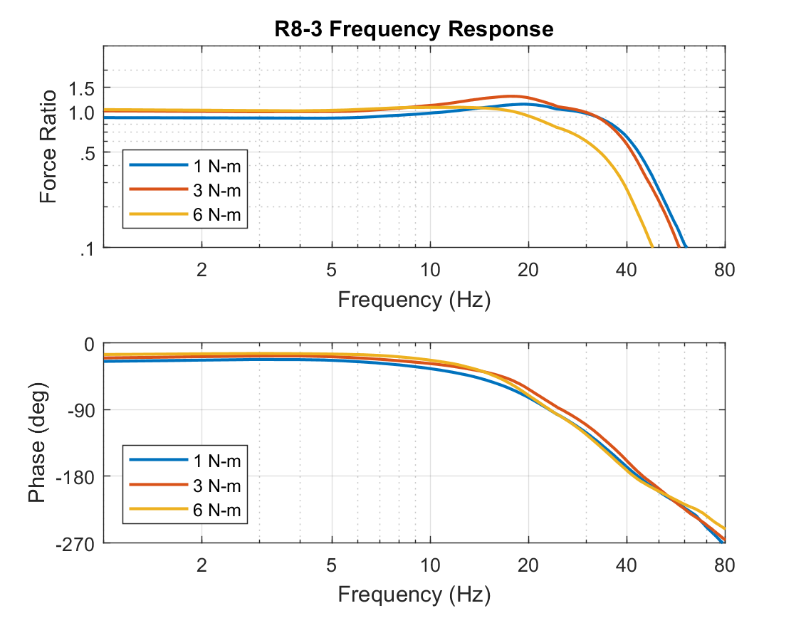
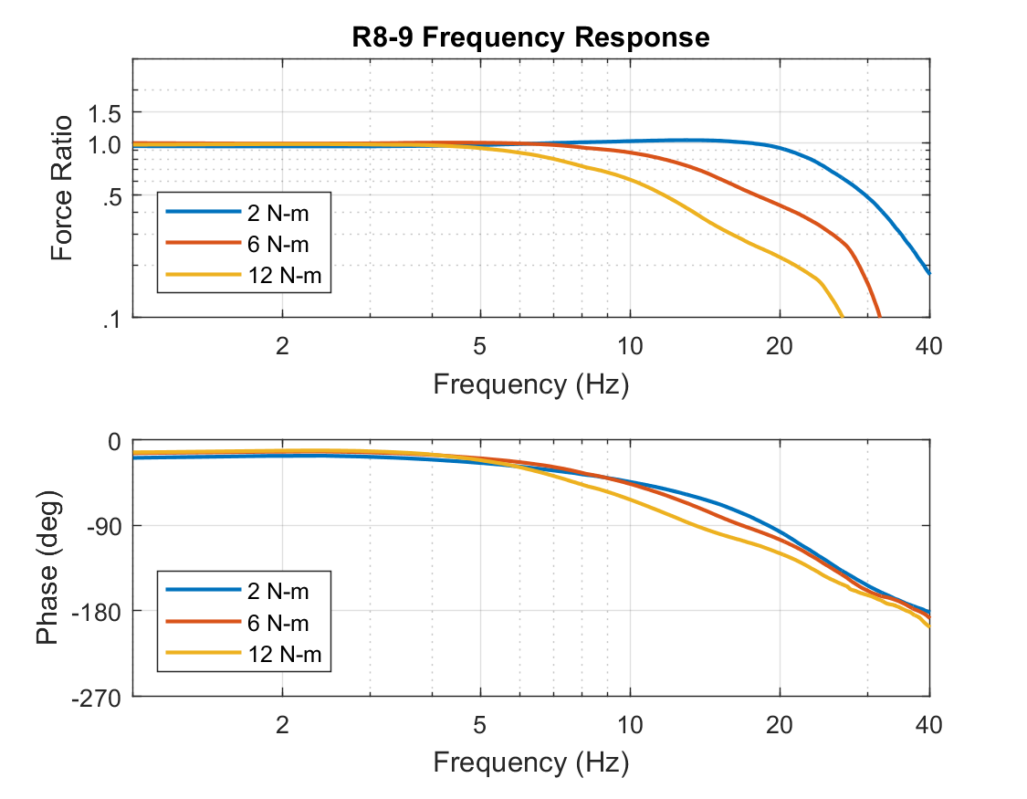
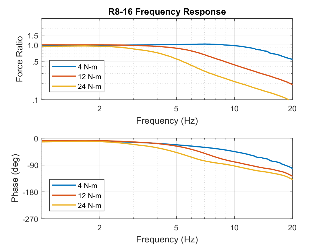
Frequency Response (Bode Plots)
Because the T-Series and R-Series actuators are mechanically compliant, there is a limit to how rapidly they can react and track to desired commands. Overall, the actuators are designed to be able to replicate human-like motion, but the details of their frequency response depends on the model of the actuator and the details of its commanded action.
The plots below were generated with a mechanically fixed output and tracking a sinusoidal commanded effort of different amplitudes. The ranges shown below are approximate and assume an actuator running at 36V in normal room-temperature conditions without additional cooling. The gains that are used when controlling an actuator greatly effects the frequency response. The plots below use an effort Kp approximately 2X the default value that ships with a new actuator.
Mechanical Information
| Actuator Model | Gear Ratio | Spring Stiffness (Non-Linear) |
Output Bearing Capacity |
|---|---|---|---|
T5-1 |
272.222 : 1 |
Min: ~10 Nm / rad |
Radial Load Rating Axial Load Rating Cross-Moment Load Rating |
T5-4 |
762.222 : 1 |
Min: ~20 Nm / rad |
|
T5-9 |
1742.222 : 1 |
Min: ~50 Nm / rad |
|
T8-3 / T8-3+ |
272.222 : 1 |
Min: ~50 Nm / rad |
|
T8-9 / T8-9+ |
762.222 : 1 |
Min: ~70 Nm / rad |
|
T8-16 / T8-16+ |
1462.222 : 1 |
Min: ~140 Nm / rad |
|
T25-8 / R25-8 |
253.657 : 1 |
Min: ~100 Nm / rad |
Radial Load Rating Axial Load Rating Cross-Moment Load Rating |
T25-20 / R25-20 |
638.682 : 1 |
||
T25-40 / R25-40 |
1301.345 : 1 |
Electrical / Motor Information
| Actuator Model | Approximate Torque Constant | Approximate Speed Constant | Motor Winding Resistance | Motor Inertia | Gear Inertia @ Motor |
|---|---|---|---|---|---|
T5-1 |
1.1 Nm / A |
5.6 RPM / V |
10.0 Ω |
43 gmm^2 |
18 gmm^2 |
T5-4 |
3.1 Nm / A |
2.0 RPM / V |
16 gmm^2 |
||
T5-9 |
7.1 Nm / A |
0.9 RPM / V |
15 gmm^2 |
||
T8-3 |
1.6 Nm / A |
3.8 RPM / V |
5.3 Ω |
85 gmm^2 |
11 gmm^2 |
T8-9 |
4.6 Nm / A |
1.3 RPM / V |
6 gmm^2 |
||
T8-16 |
8.8 Nm / A |
0.7 RPM / V |
5 gmm^2 |
||
T8-3+ |
1.8 Nm / A |
3.8 RPM / V |
3.0 Ω |
60 gmm^2 |
11 gmm^2 |
T8-9+ |
5.1 Nm / A |
1.3 RPM / V |
6 gmm^2 |
||
T8-16+ |
9.8 Nm / A |
0.7 RPM / V |
5 gmm^2 |
||
T25-8 |
1.6 Nm / A |
4.2 RPM / V |
0.5 Ω |
364 gmm^2 |
|
T25-20 |
4.0 Nm / A |
1.7 RPM / V |
|||
T25-40 |
8.2 Nm / A |
0.8 RPM / V |
Operating Environment
| Actuator Series | Environmental Conditions |
|---|---|
T-Series |
Designed to IP 65 |
R-Series |
Designed to IP 67 |
EMC Certifications
| Actuator Series | Certifications | Declarations of Conformity |
|---|---|---|
T-Series |
FCC Part 15 |
|
R-Series |
FCC Part 15 |
|
T-Series & |
EU 2023/1230 (for partly completed machinery) |
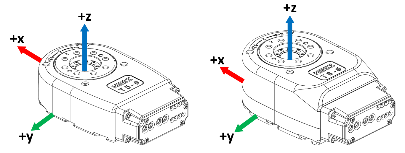
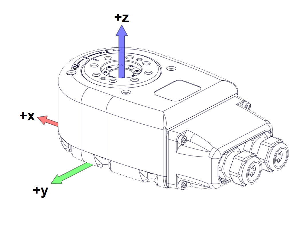
Reference Frames
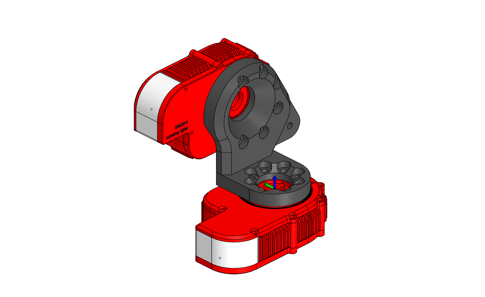
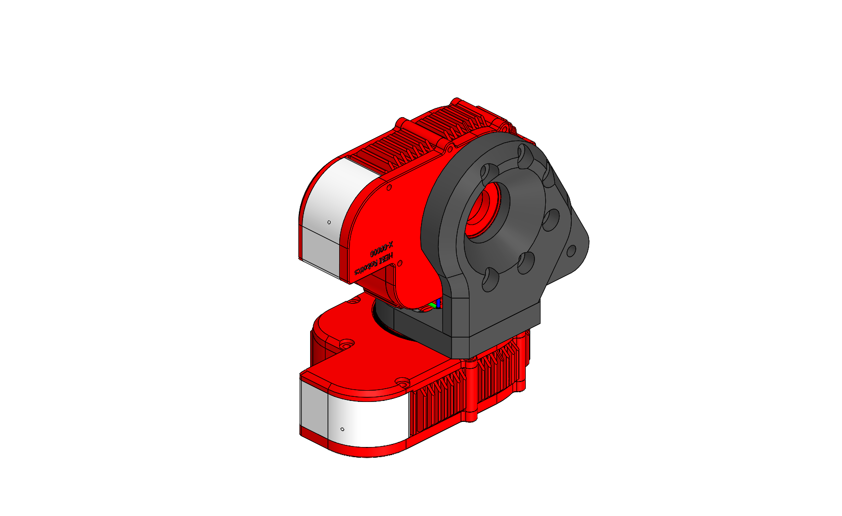
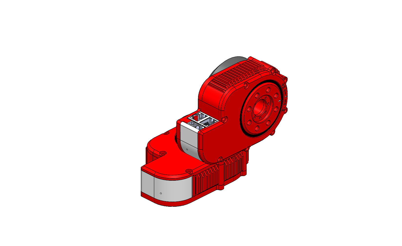
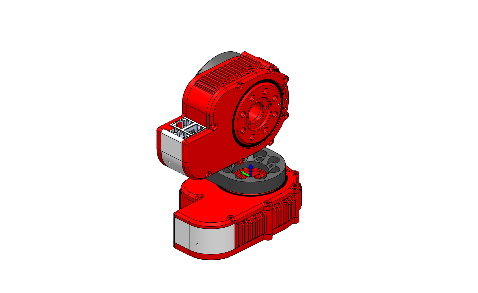
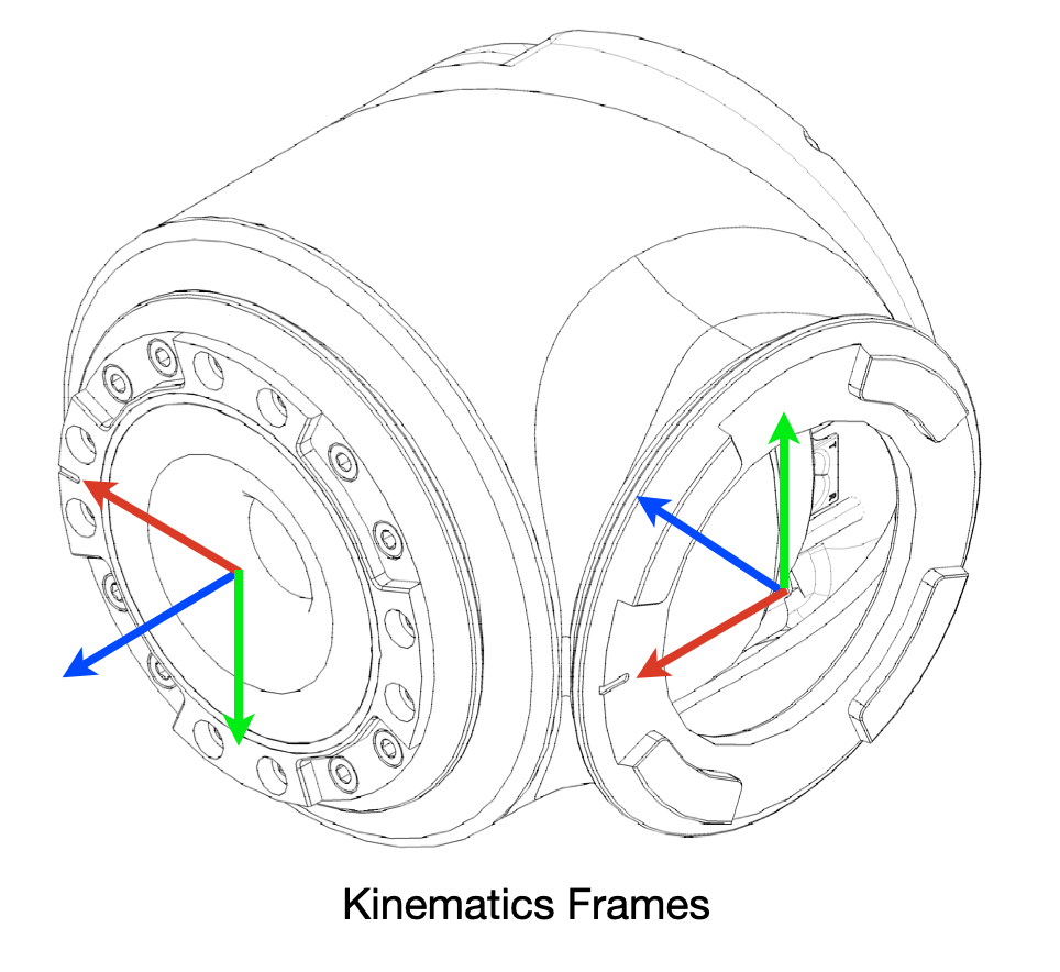
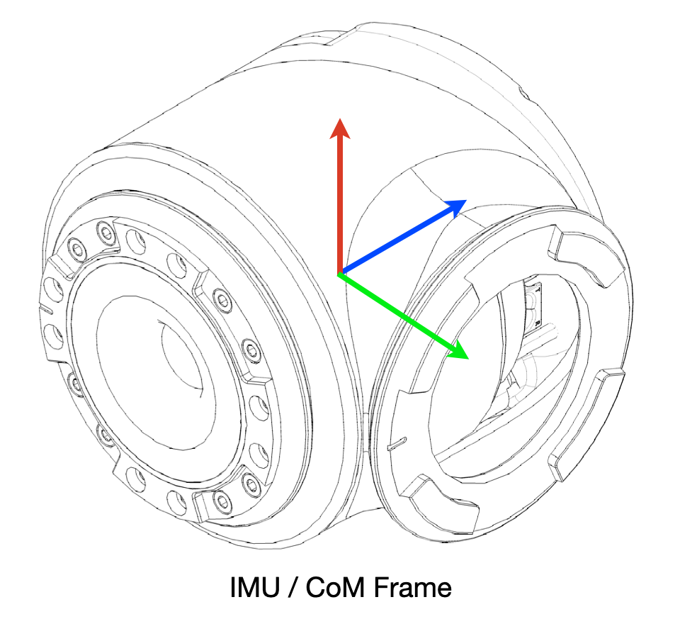
The reference frames for the T-Series and R-Series Actuators are shown in the images below.
The origin of the coordinate frames for the actuator housing are on the back plane of the housing, centered on the axis of rotation. This is the frame in which the IMU feedback is reported, and it is also the frame that is used for kinematics calculations in the various APIs and the HRDF file format. The coordinate frames are also physically engraved on the housing of each actuator.
The origin of the output frame of the actuator is centered on the output shaft on the mounting surface of the output and rotates with the output. The X-axis of the output frame points toward the zero tick mark on the output shaft.
Default Gains (T-Series & R-Series)
We have provided downloadable recommended default gains for all control strategies of each of our T-Series and R-Series modules. Note that these gains should still be tuned for best performance depending on the particular application. For almost all applications we recommend using Strategy 4.
| Module Type | Strategy 4 (recommended) | Strategy 3 | Strategy 2 | |
|---|---|---|---|---|
T5-1 |
||||
T5-4 |
||||
T5-9 |
||||
T8-3 / T8-3+ |
||||
T8-9 / T8-9+ |
||||
T8-16 / T8-16+ |
||||
T25-8 / R25-8 |
||||
T25-20 / R25-20 |
||||
T25-40 / R25-40 |
Wiring
T-Series and R-Series actuators were designed to simplify traditional wiring pain points and wire loops by incorporating a through hole. A multi-port switch for daisy chaining POF communication as well as a terminal block for power daisy chaining.
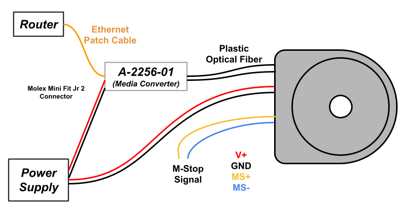
Wiring Block Diagram
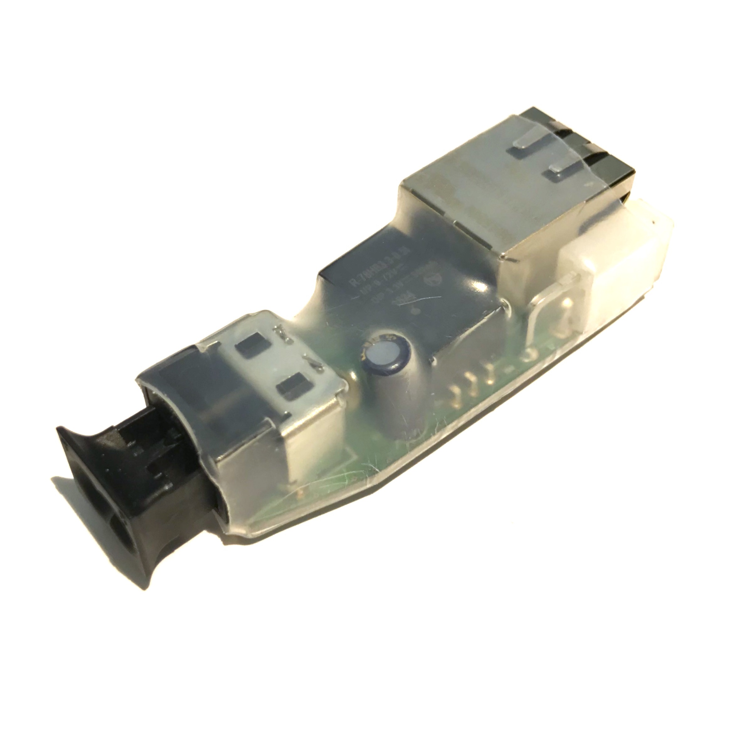
Here is a simple Block Diagram showing the wiring setup for the T-Series and R-Series Actuators. All electronics shall be used with a 24-48V power supply. The communications runs off of 100 Mbps Ethernet converted in the Media Converter to plastic optical fiber (POF) into the actuator.
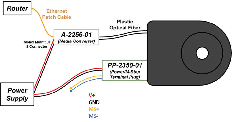
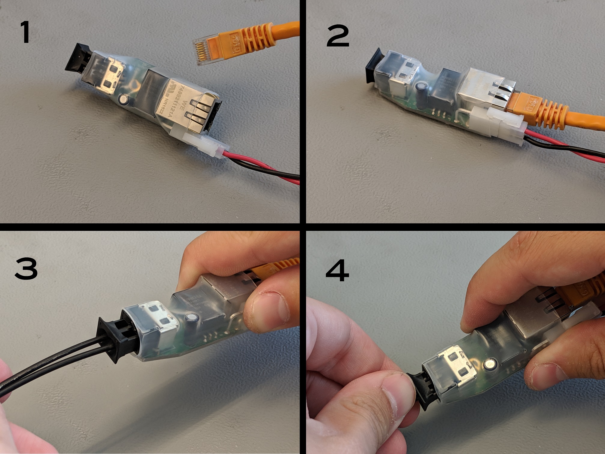
A POF-Ethernet Media Converter is used to connect the T-Series and R-Series Actuators to the network. The converter can run off the same 24-48VDC as the actuators and can convert 100 Mbps RJ45 Ethernet communication to 2.2mm plastic optical fiber (POF) communication of the same 100 Mbps Ethernet.
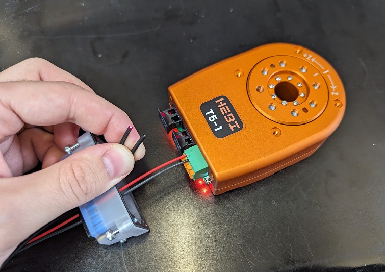
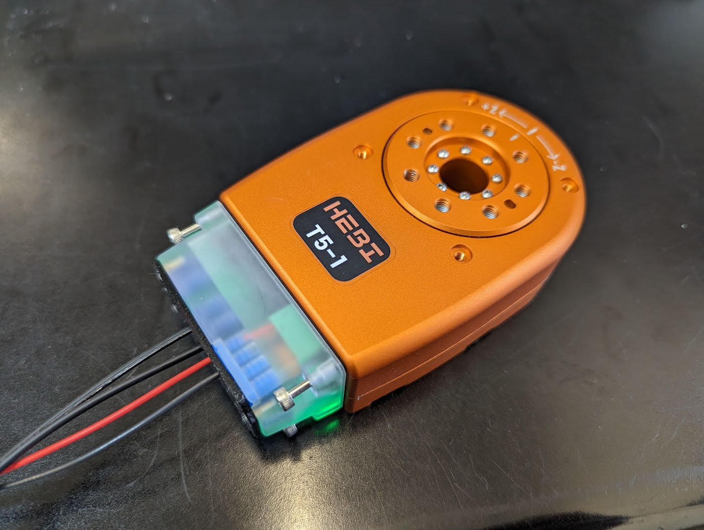
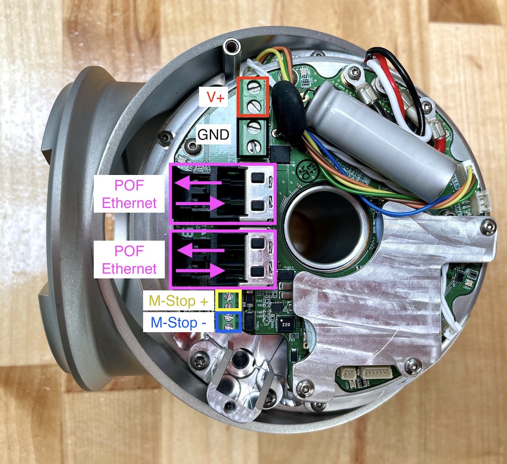
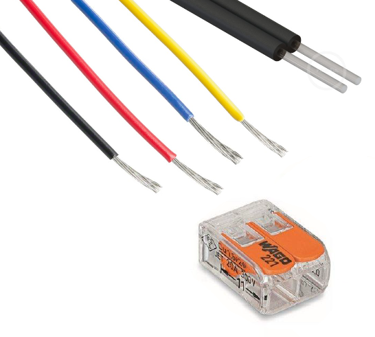
T-Series Wire Seals
Wires need to be fed thru wire seals for best sealing (~IP64). |
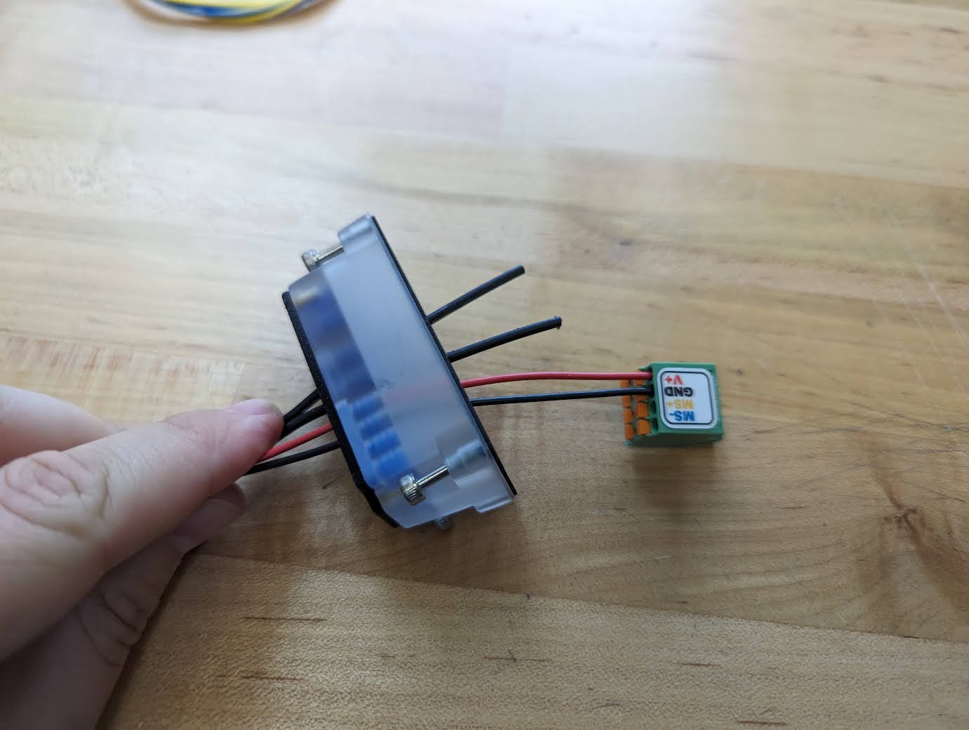
Power wires connect to the green terminal block which has 2 ports for each cable enabling daisy-chaining. |
|
|
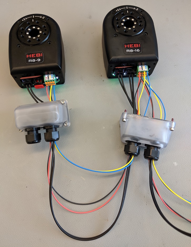
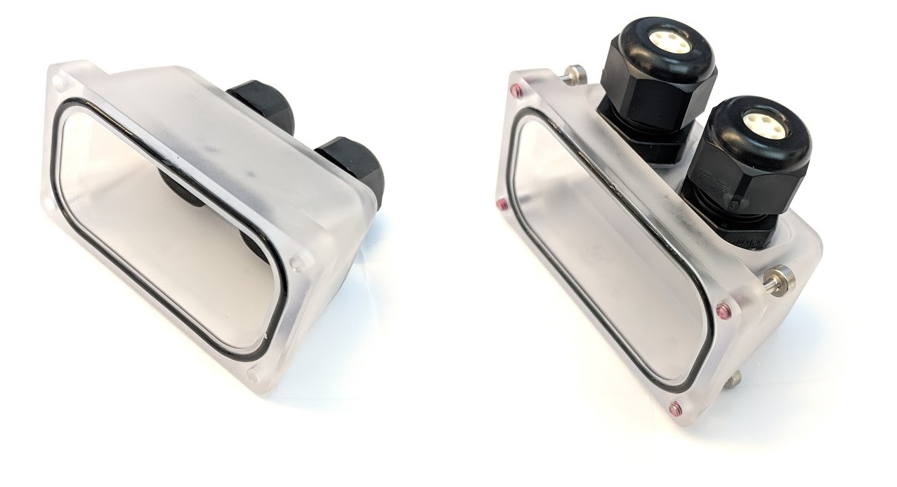
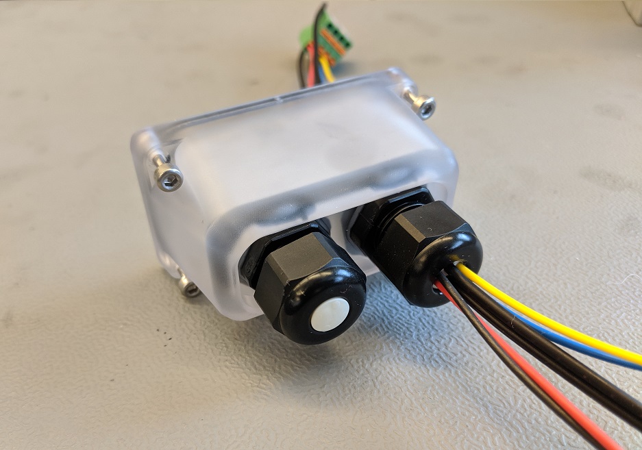
R-Series Cord Grips
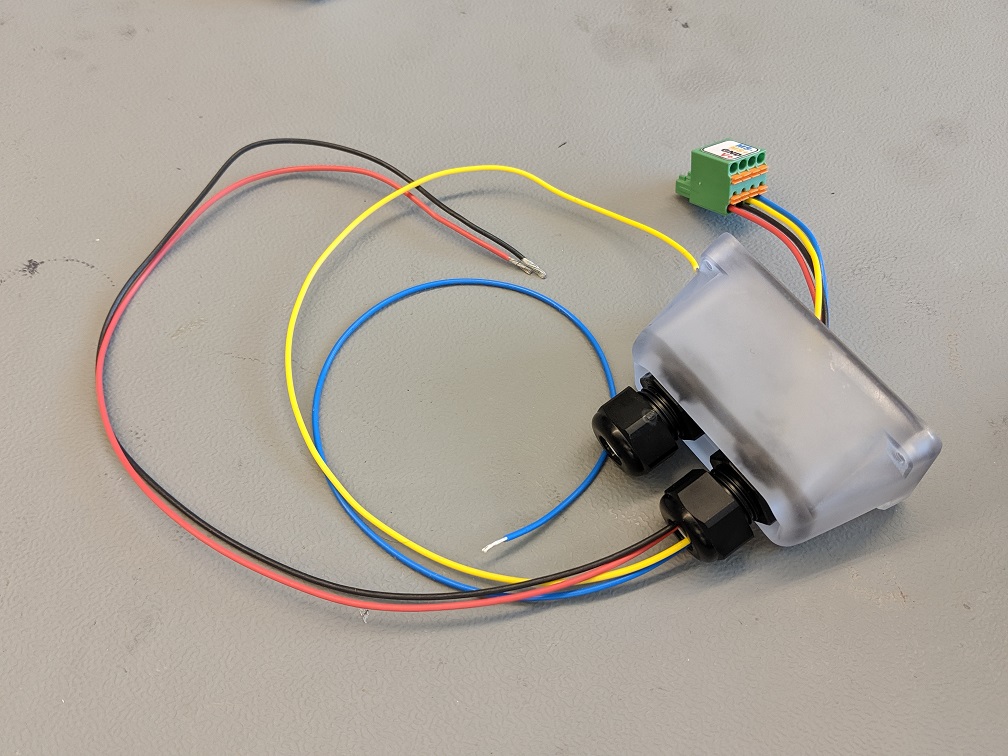
Wires need to be fed thru cord grips for sealing. |
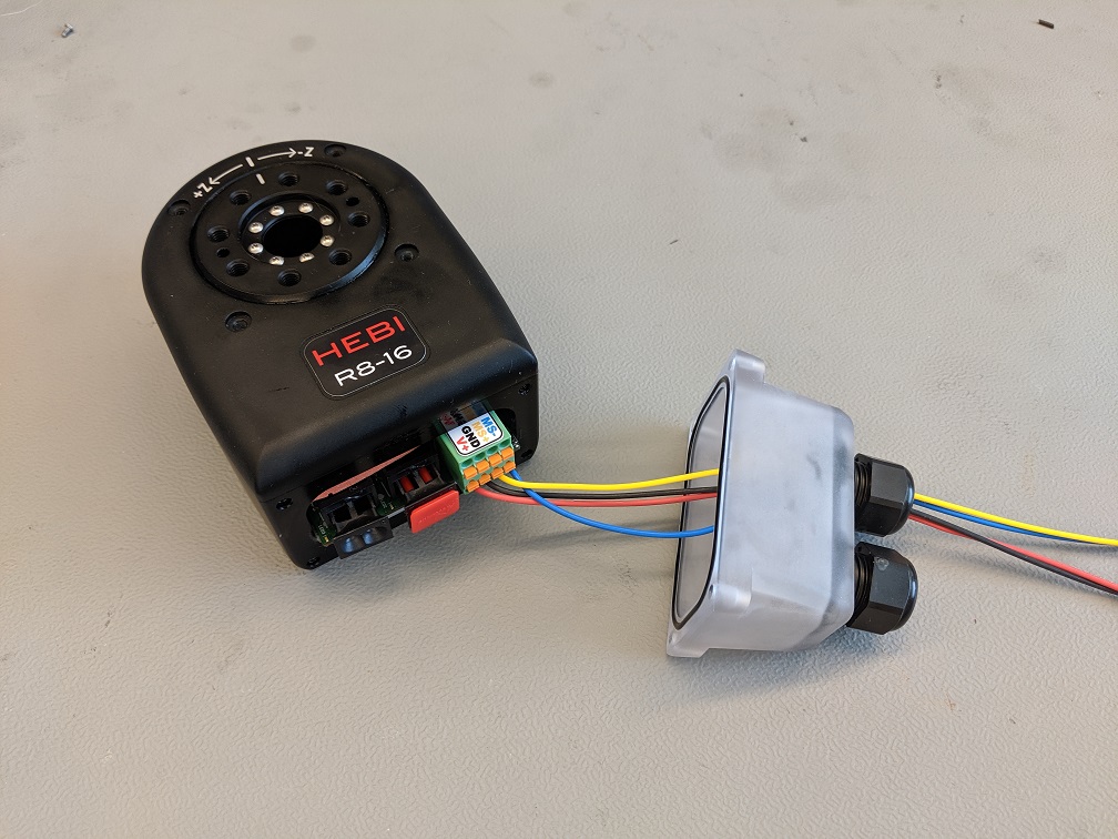
Power wires connect to the green terminal block which has 2 ports for each cable enabling daisy-chaining. |
|
|
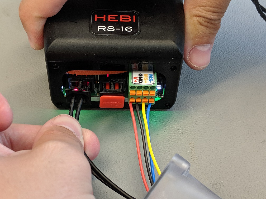
M-Stop Wiring
An M-Stop (motor-stop) button can be wired to the T-Series and R-Series Actuators' terminal plug for additional safety. We recommend using a lower voltage (5V) to power the M-Stop for reduced power dissipation. Below are examples of how the MS+ and MS- lines can be wired if you want to use an M-Stop Button in your system:
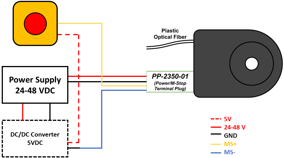
M-Stop connected to a lower voltage source to reduce power dissipation (preferred configuration). |
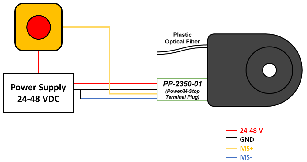
M-Stop connected to same power supply as the actuator. |
The MS+ and MS- lines are the "M-Stop" input for the Actuators. They correspond to the "M-Stop Strategy" setting on the actuators that can be selected from the Scope Application on the 'Gains' Tab shown in the screenshot below:
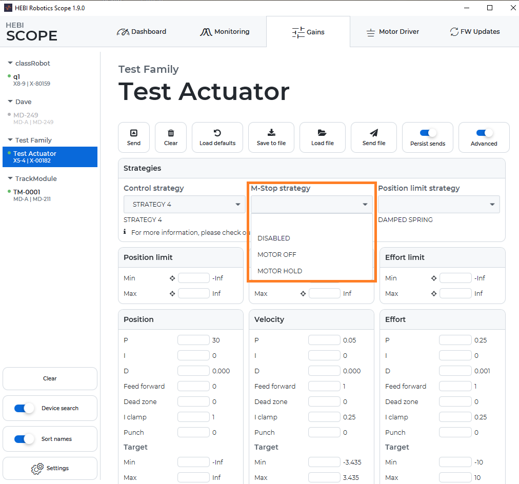
The actuators can be set to have different behaviors when the M-Stop is triggered, described in the table below.
| Make sure to use the "Persist Sends" option when setting the M-Stop Strategy in order to maintain setting after actuator the actuator is reset or turned off and on. |
M-Stop Strategy |
Description |
Disabled |
The M-Stop input is ignored. The actuator runs normally no matter what voltage is applied to these lines. |
Motor Off |
The M-Stop pins require voltage (5V-48VDC) for the actuator to run. When voltage is removed, the motor in the actuator is deactivated (set to Control Strategy Off) and the actuator is backdrivable. The status LED will blink yellow. |
Motor Hold |
The M-Stop pins require voltage (5V-48VDC) for the actuator to run. When voltage is removed, the motor in the actuator is controlled to maintain its current position. The status LED will blink yellow. |
Mechanically Mounting Actuators
The T-Series and R-Series Actuators have threaded holes for M5 metric screws on their output and bottom sides and four M3 threaded holes on the front plate for mounting. Additionally, there are two 3mm Dowel Pin holes that are spaced 35mm apart symmetric from the center bore on both the output and input interfaces to help with bracket alignment. If you are using standard HEBI connection parts, the appropriate hardware is provided.
Check out the standard T-Series & R-Series Accessories
T5 Reference Drawing: T5 Dimensional Interface Drawing
T8 Reference Drawing: T8 Dimensional Interface Drawing
R8 Reference Drawing: R8 Dimensional Interface Drawing
| Be careful to use the appropriate length screws when mounting the actuators. Using screws that are too long may damage the actuator if they are tightened while bottomed out in the threaded holes. |
| Be sure to only use Stainless Steel or other Corrosion-Resistant hardware with the R-Series Actuators. This is to prevent the hardware from seizing due to corrosion. |
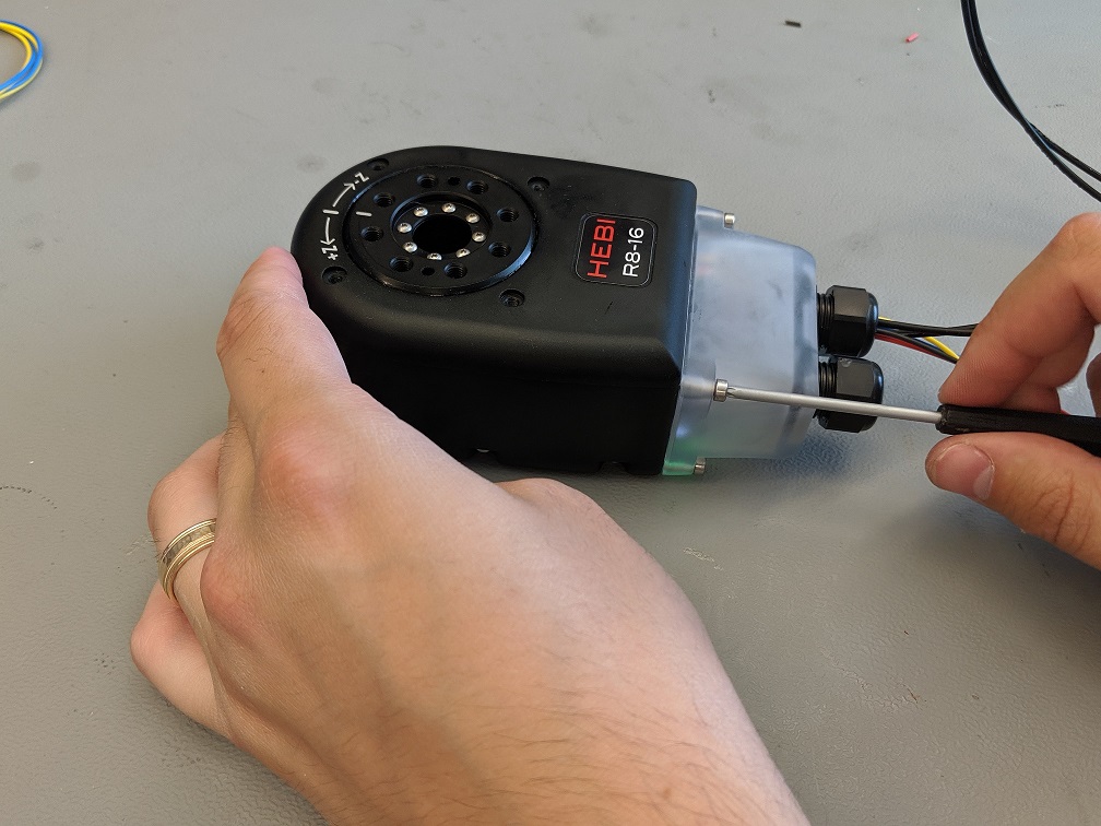
Sealing R-Series Actuators
The R-Series actuators are designed to be sealed to an IP67 rating. In order to achieve the seal, the connector cover needs to be fully installed to the back end of the Actuator.
| The connector covers (A-2204-01A and A-2204-01B) have an o-ring that will seal against the back of the actuator. Using the silicone grease in the connection toolbox, fully grease the o-ring before attaching the cover. |
| If only one cord grip has wires coming through it, replace the unused cord grip insert with a solid plug (PP-2408-01) and tighten down the cord grip. |
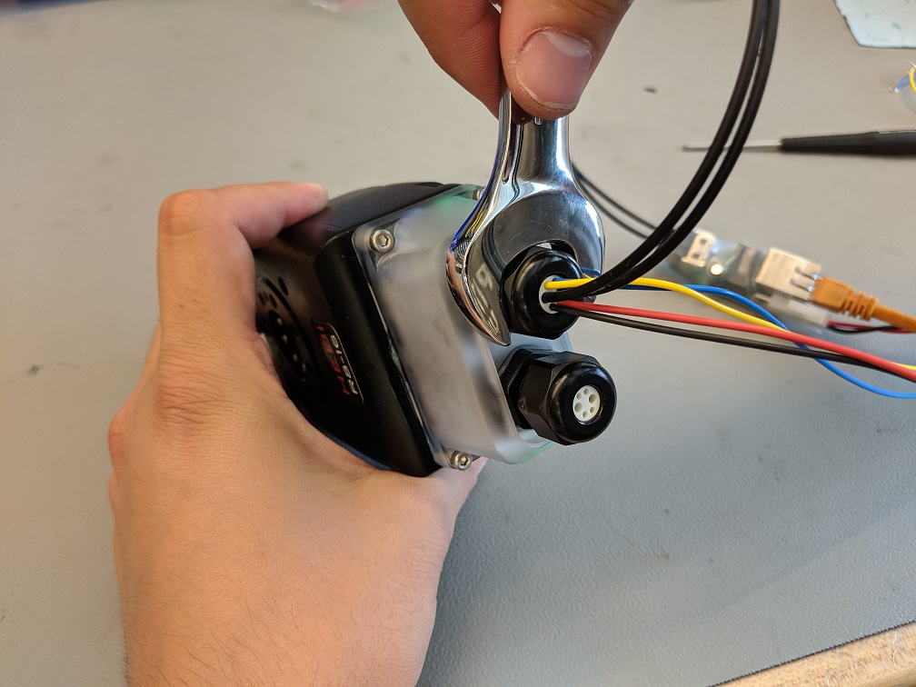
-
Lightly pull the slack in the cables through the cord grips to bring the connector cover up agaisnt the actuator. Make sure the terminal block does not disconnect from the actuator.
-
While holding the connector cover up against the actuator, screw down the captive M3 bolts.
-
Use a 19mm (or 3/4") open wrench to tighten down the cord grip rubber insert around the wires.
| It is important to note that the media converter and other electronics, like the power supply, are not sealed. Make sure there is enough cable length to keep the electronics in some kind of protective case or box if the actuators are being used in a dirty or wet environment. |
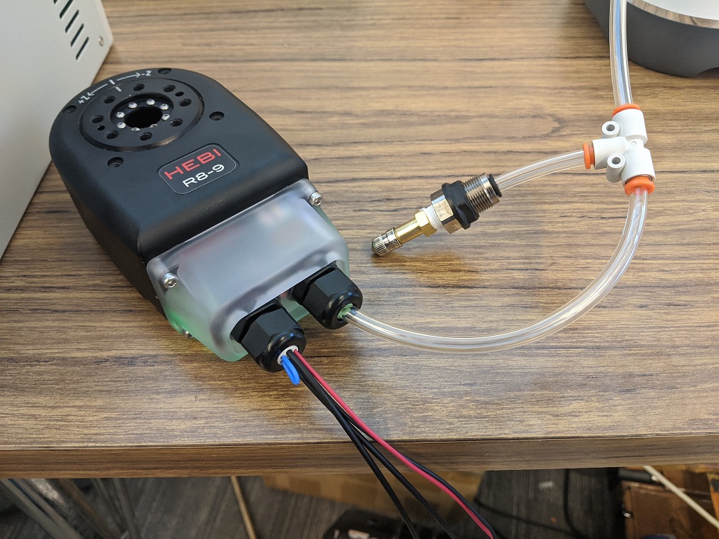
Internal Pressure (R-Series)
In addition to being sealed for intermittent wet use, R-Series actuators contain an internal pressure sensor that can be accessed on the pressure in the actuator feedback.
-
Readings are in
kPaThe readings from the sensor are absolute pressure, which is the sum of gauge pressure and atmospheric pressure. The reading of an unpressurized actuator will fluctuate slightly with changes atmospheric pressure and temperature. -
Standard Reading:
~101 kPa(1 atm or 14.7 psi) -
Minimum Internal Pressure :
10 kPa(1.5 psi) -
Maximum Internal Pressure :
300 kPa(43.5 psi)
-
Include a valve
When you are internally pressurizing R-Series actuators it is always good to have some kind of valve incorporated for adding and removing air from the system.
| Remember to remove all internal pressure from actuators before disassemblying wiring of actuators. This includes prior to loosening cord grips and screws on connector covers. This will prevent causing harm to yourself or damage to actuator’s o-rings and other components. |
| In most cases it is best to use the M-stop (blue and yellow) wiring, but if you determine you don’t need it, then you can always loop a wire in the last 2 open cord grip holes to keep the Actuator sealed (shown in image below). |
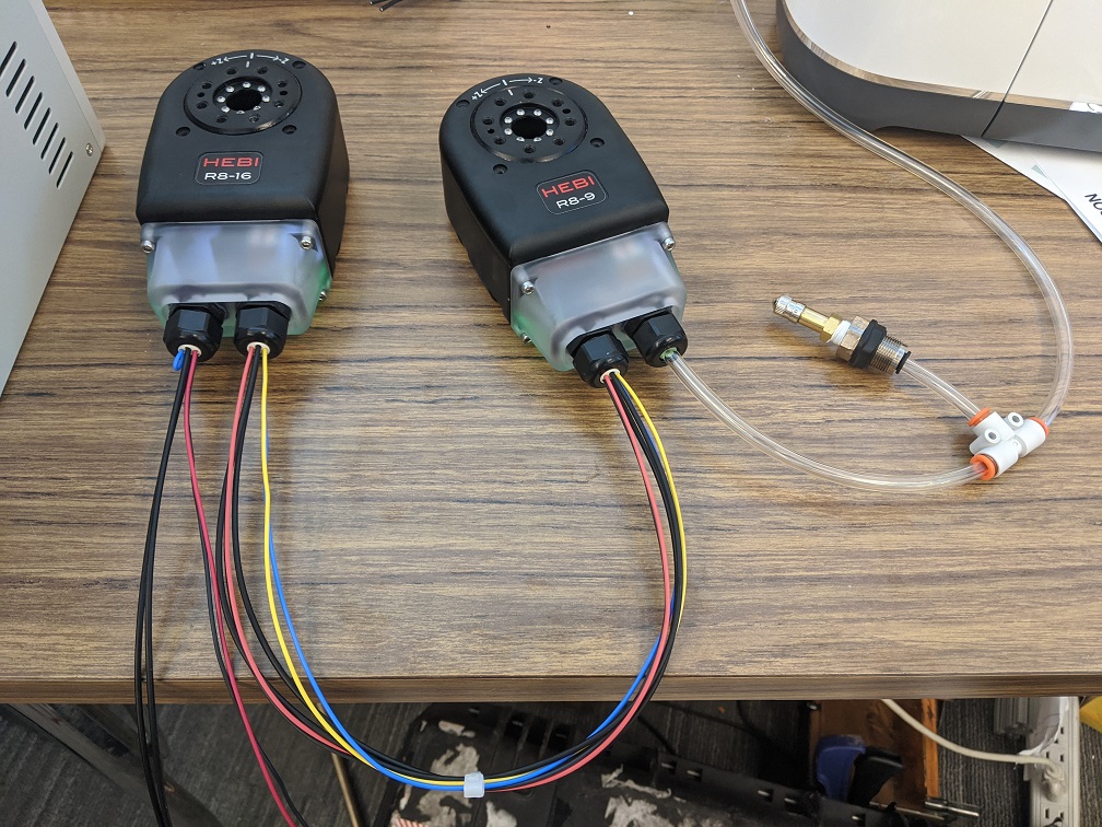
Plug the last Cord Grip with Solid Wire
Even though the R-Series actuators are sealed, air is still able to pass through the wiring of the actuators. Whether you are pressurizing a single or multiple actuators, the last cord grip in your chain should use solid core wire for the power and M-stop lines. This will prevent air from escaping from the pressurized system.
We recommend using the following solid core wires:
-
Black 18AWG Solid Core Wire: Alpha Wire 6715S BK005
-
Red 18AWG Solid Core Wire: Alpha Wire 6715S RD005
| Solid core wires work well with the WAGO wire nuts and a standard HEBI flying-lead power cable (both included in R-Series standard wiring kit). |

Alternative method: custom tether pressurization adapter
As an alternative experiment, a group of 5 actuators were daisy-chained together using the standing wiring cables and a tether pressurization adapter. This custom adapter allows for pressure to be added to the system from the tether instead of the end effector actuator and prevents air from escaping back to your power supply with solid core wire.
| A constant air supply of ~250 kPa (absolute pressure) was supplied from the tether with the last module having a solid plug. |
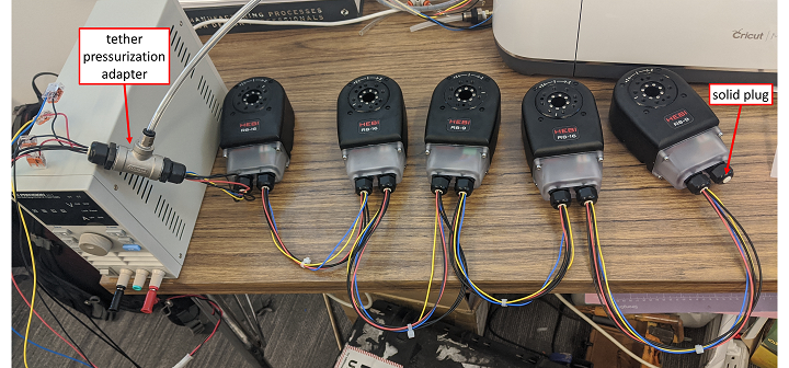
The following plots show the difference between using using only stranded wires and using the solid core wires in from the tether pressurization adapter.
| The POF (plastic optical fiber) cables fully block air flow and do not need to be changed. |
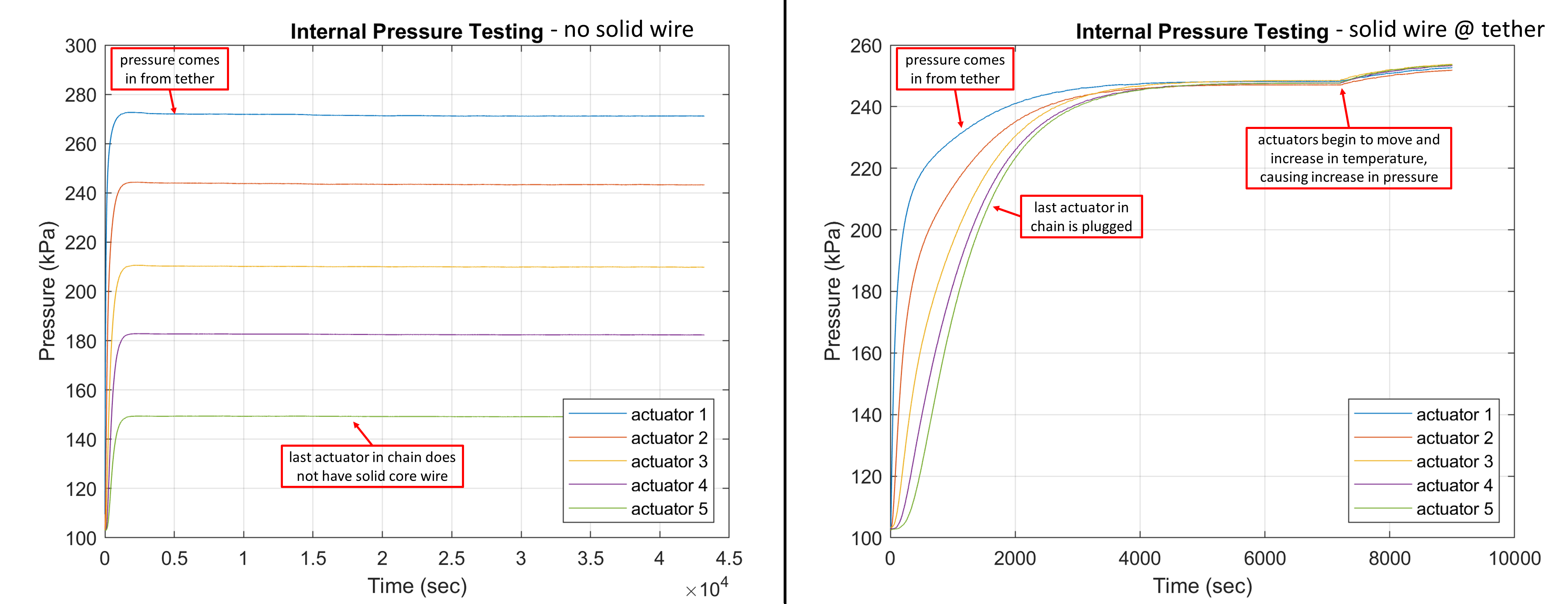
| From the plot on the left, the pressure drop between actuators in steady-state appears to be correlated to length of wire between the two actuators. The longer the wires, the larger the pressure drop. Additionally, pressure and temperature are directly proportional, as the actuator temperature increases the internal pressure will also increase. |
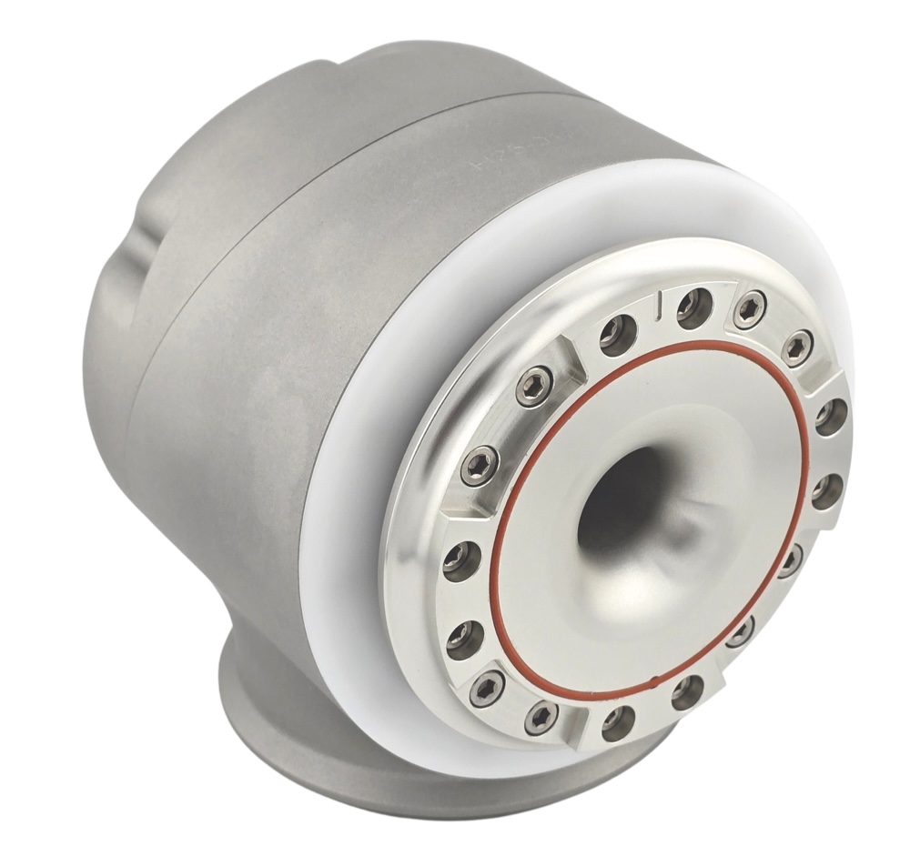
H-Series Actuators
The H-Series Actuators are 'smart' actuators that integrate a frameless BLDC motor, strain wave reducer, encoders, and control electronics into a modular joint that runs on standard DC voltages and communicates using standard 10/100Mbps Ethernet over plastic optical fiber (POF). These actuators are designed to function as full-featured robotic components and enable the simultaneous control of position, velocity, and torque. Each actuator also has a wide range of other sensors, all of which can be easily accessed in the the various APIs. The H-Series Actuators are designed for precise, powerful, and robust performance in a variety of applications.
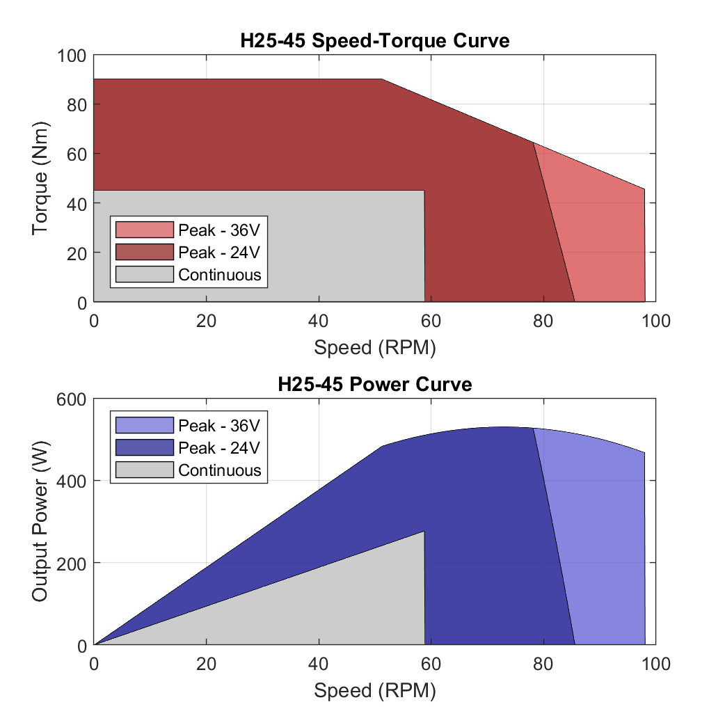
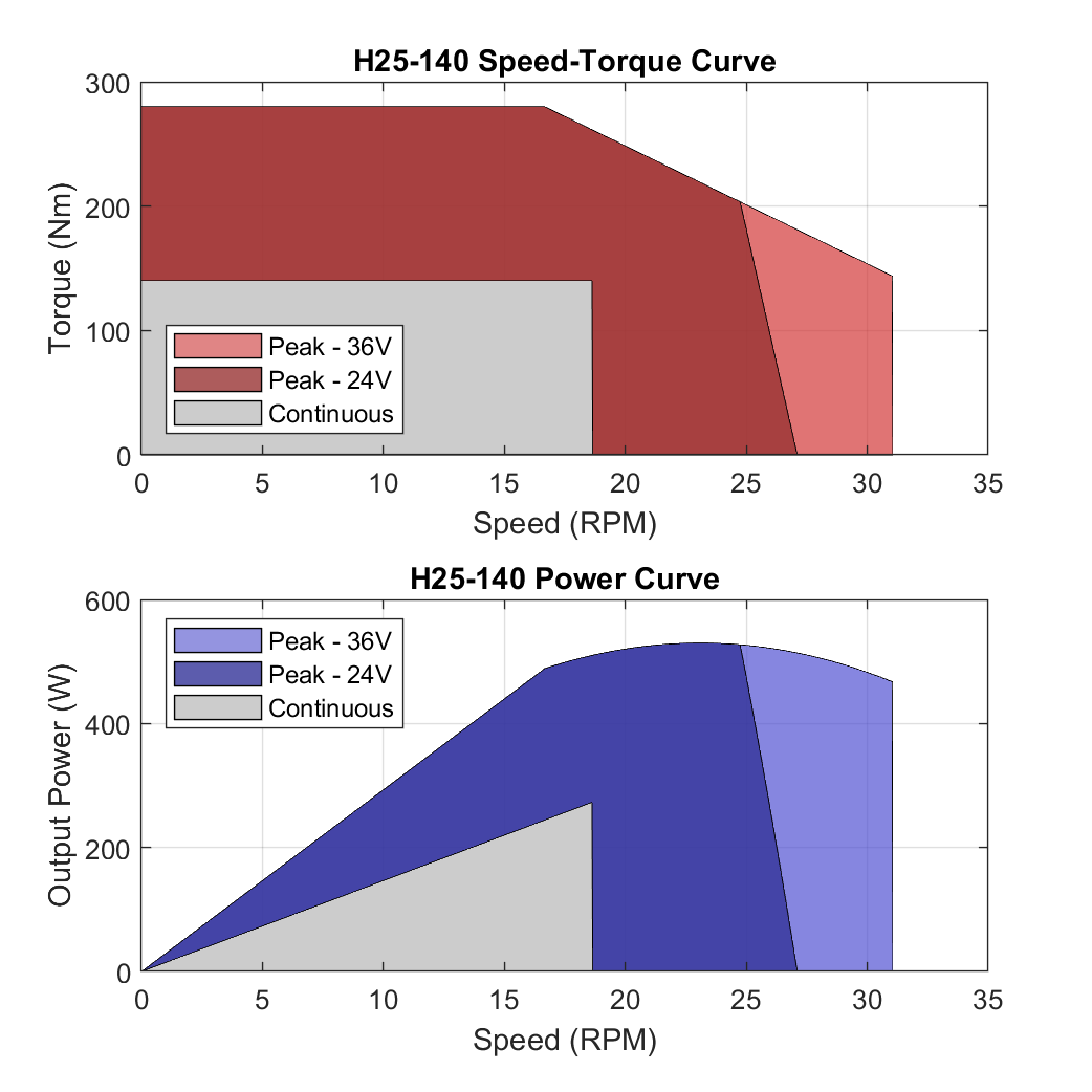
Speed-Torque Curves
The actuators have a range where they can perform continuously, as well as a peak range where they can perform intermittently. While H-Series actuators are rated for running at 24V, they are capable of increased intermittent output at higher voltages. We recommend running the actuators at 36V - 48V for most applications.
While the actuators can be run at bus voltages up to 48V, the performance is limited in firmware by capping the applied winding current to a maximum torque vales, as well as limit to approximately 500W of mechanical output power. The ranges shown below are approximate and assume an actuator in normal room-temperature conditions without additional cooling.

Mechanical Information
| Actuator Model | Gear Ratio | Output Bearing Capacity |
|---|---|---|
H25-45 |
51 : 1 |
Basic Load Rating Cross-Moment Load Rating |
H25-90 |
101 : 1 |
|
H25-140 |
161 : 1 |
Electrical / Motor Information
| Actuator Model | Approximate Torque Constant | Approximate Speed Constant | Motor Winding Resistance | Rotor Inertia @ Motor |
|---|---|---|---|---|
H25-45 |
1.1 Nm / A |
5.6 RPM / V |
0.11 Ω |
2500 gcm^2 |
H25-90 |
3.1 Nm / A |
2.0 RPM / V |
||
H25-140 |
7.1 Nm / A |
0.9 RPM / V |
Operating Environment
| Actuator Series | Environmental Conditions |
|---|---|
H-Series |
Designed to IP 65 |
Regulatory Certifications
| Actuator Series | Certifications | Declarations of Conformity |
|---|---|---|
H-Series |
EMC-2014/30/EU MIL-STD-810G 514.6, 516.6 (Shock/Vibration) EU 2023/1230 (for partly completed machinery) |
Reference Frames
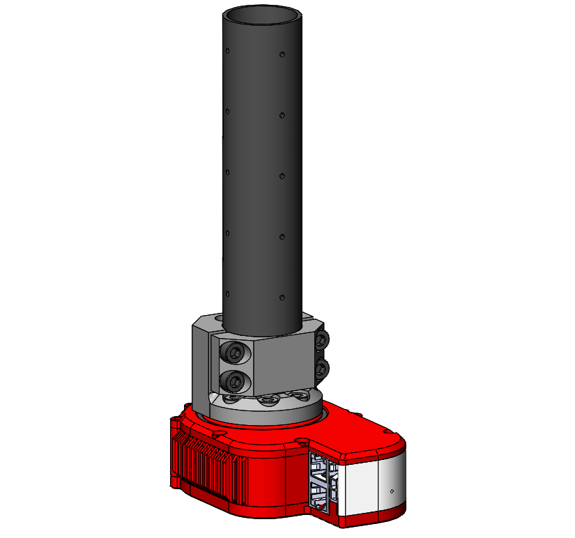
The reference frames for the H-Series Actuators are shown in the images below. The frames are consistent in both the 'forward' and 'reverse' orientations of the actuator.
The image on the left show the frames that are used for kinematics calculations in the various APIs and the HRDF file format. The frame on the output has its Z-axis aligned with the rotation axis, with the X-axis pointing to the output zero tick mark. The frame on the housing has its Z-axis aligned with the centerline of the clamping interface, with the X-axis pointing to the housing tick mark.
The image on the right is the frame that IMU measurements are reported in, and is also the "Center of Mass" frame reported from the kinematics APIs.
Default Gains (H-Series)
We have provided downloadable recommended default gains for the H-Series. H-Series only have one control strategy, Strategy 5. Note that these gains should still be tuned for best performance depending on the particular application.
| Module Type | Strategy 5 |
|---|---|
H25-45 |
|
H25-90 |
|
H25-140 |
Wiring
H-Series actuators are designed to simplify traditional wiring pain points and wire loops by incorporating a through hole. It includes two ports for daisy chaining POF communication as well as a terminal block for daisy chaining power and M-Stop.
Wiring Block Diagram
Here is a simple Block Diagram showing the wiring setup for the H-Series Actuator. All electronics shall be used with a 24-48V power supply. The communication is 100 Mbps Ethernet converted in the Media Converter from an RJ45 connection to Plastic Optical Fiber into the Actuator. Power, Ethernet, and M-Stop can daisy-chain between actuators.
M-Stop Wiring
The H-Series supports the same M-Stop wiring and setup as the R/T-Series actuators.
|
For H-Series actuators that do not have a brake, the actuator will be free to move when the M-Stop is triggered. For actuators that have a brake, the brake will engage when the M-Stop is triggered, which will hold the actuator in place. The brake will disengage when the M-Stop is released and commands are sent. Unlike the T-Series and R-Series actuators, the H-Series actuators do not support a |
Mechanically Mounting Actuators
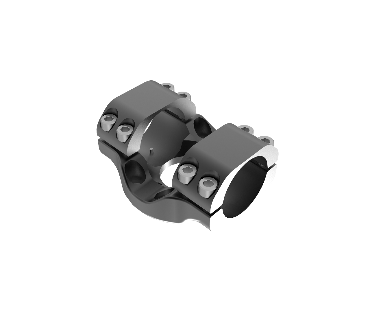
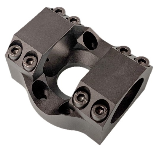
The H-Series actuators have collar clamps that are designed to attach them to other actuators, links, and assemblies.
H25 Reference Drawing: H25 Dimensional Interface Drawing
H25 Collar Clamp Reference Drawing: H25 Collar Clamp Drawing
H25 Arm Links CAD Folder: H25 Arm Links
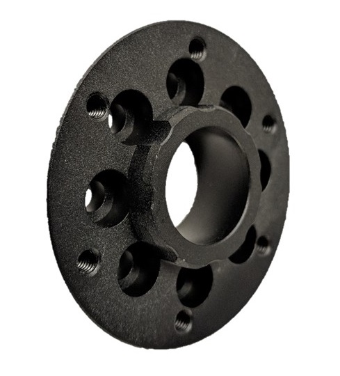
H25 Input Adapter Reference Drawing: H25 Input Adapter
H25 Output Adapter Reference Drawing: H25 Output Adapter
| Be sure to only use Stainless Steel or other Corrosion-Resistant hardware with the H-Series Actuators. This is to prevent the hardware from seizing due to corrosion. |
Actuator Feedback
All actuators (X/R/T/H-Series and Motor Drivers) provide all the feedback below when feedback is requested. Feedback can be requested at rates up to 1 kHz. Wherever possible values are in SI units.
| Parameter | Units | Description |
|---|---|---|
|
|
The current time from the system clock used by the API. This is a single value that corresponds to all feedback at this timestep. |
|
|
The system time when feedback was received by each module. The most recent of these times is what is reported as the single |
|
|
The system time when feedback requests were sent to each module. |
|
|
The hardware timestamp when each module in the group transmitted its feedback. Time initializes at 0 when a module is powered on. |
|
|
The hardware timestamp when each module in the group received a request for feedback. Time initializes at 0 when a module is powered on. |
|
|
Sensed position (absolute) of the output of an actuator. T-Series and R-Series Note: Once the actuator is powered on, it reports its position continuously and unlimited in either direction. If you go outside the +/- 4 rotation range and restart the actuator, the reported position from the encoder will ‘wrap around’ and initialize within +/- 4 rotations. |
|
|
Sensed velocity at the output of an actuator. |
|
|
Sensed force or torque (absolute) at the output of an actuator. |
|
|
The currently commanded |
|
|
The currently commanded |
|
|
The currently commanded |
|
|
In control strategies 2 and 4, this is the torque or force command going to the inner torque PID loop. |
|
|
The currently commanded |
|
|
The internal deflection of the spring inside an actuator. This value is used with a calibrated spring constant in each actuator to report the actuator’s |
|
|
The velocity of the internal spring’s deflection. |
|
|
The position of an actuator’s internal motor before the gear reduction. Initializes at zero when an actuator is first powered on. |
|
|
The velocity an actuator’s internal motor before the gear reduction. |
|
|
A module’s sensed 3-DoF acceleration from an internal IMU, including gravity. Note that this is the sensed motion of the actuator body itself, not the actuator’s output. Depending on the API, XYZ values are combined together into a single vector or returned individually. |
|
|
A module’s sensed 3-DoF angular velocity from an internal IMU. Note that this is the sensed motion of the actuator body itself, not the actuator’s output. Depending on the API, XYZ values are combined together into a single vector or returned individually. |
|
|
A module’s 3-DoF orientation based on an onboard complementary filter. The heading component of the estimated orientation will drift over time, as the filter uses only accelerometers and gyros. Depending on the API, quaternion components are combined together into a single vector or returned individually. |
|
|
The sensed amount of current an actuator’s motor draws at the bus voltage. |
|
|
The estimated of amount current draw of the motor windings internal to the actuator. This value is modeled based on the known motor parameters, internal motor velocity, and current. |
|
|
The sensed bus voltage into the module. |
|
|
The sensed temperature near the motor in the actuator. |
|
|
The sensed temperature of the electronics in the actuator. |
|
|
The sensed temperature of the processor in the actuator. |
|
|
The modeled housing temperature of the motor inside an actuator. |
|
|
The modeled winding temperature of the motor inside an actuator. This value is used by a safety controller that runs in the firmware of an actuator that will limit the |
|
|
The status of the M-Stop line in the module.
|
|
|
The status of the command lockout on the module, active during the
|
|
|
The status of the various temperature safety controllers on the module.
|
|
|
The status of the various motion safety controllers on an actuator.
|
|
|
RGB color values of the status LED. Depending on the API, RGB values are combined together into a single vector or returned individually. |
|
|
Internal absolute pressure of the actuator in kPa. (R-Series Only) |
Actuator Commands
The typical actuator commands for controlling motion are the same as the commands listed in the Groups section of Core Concepts. Additionally, there are direct commands for PWM and FOC current/voltage that are sometimes used in research-focused applications.
| Parameter | Units | Description |
|---|---|---|
|
|
The desired position of the output of an actuator. |
|
|
The desired velocity of the output of an actuator. |
|
|
The desired torque or force of the output of an actuator. For an actuator in the |
|
|
For an actuator in the |
|
|
For an actuator in the |
|
|
For an actuator in the |
In addition to commands related to motion, a number of hardware-specific parameters can be commanded and/or set.
| Parameter | Units | Description |
|---|---|---|
|
|
The desired user-settable name that an actuator shows up as in a |
|
|
The desired user-settable family that an actuator shows up as in a |
|
|
Boots a module from bootloader mode into application mode. |
|
|
Reboots a module. |
|
|
Saves all the settings and gains that are currently set on a module, so that they are loaded after reboot. |
|
All controller parameters are settable in the API. See Parameters and Gains in the Core Concepts section for more information. |
|
|
|
Sets the current feedback |
|
|
Sets the current |
|
|
Override RGB color values of the status LED. |
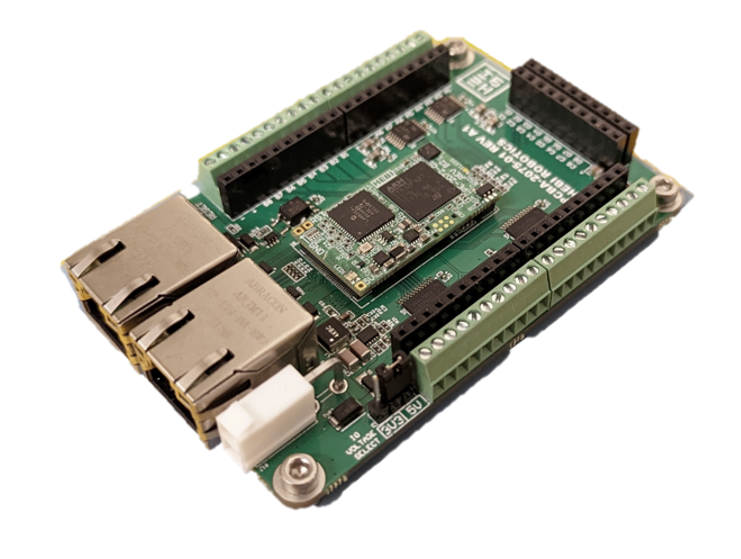
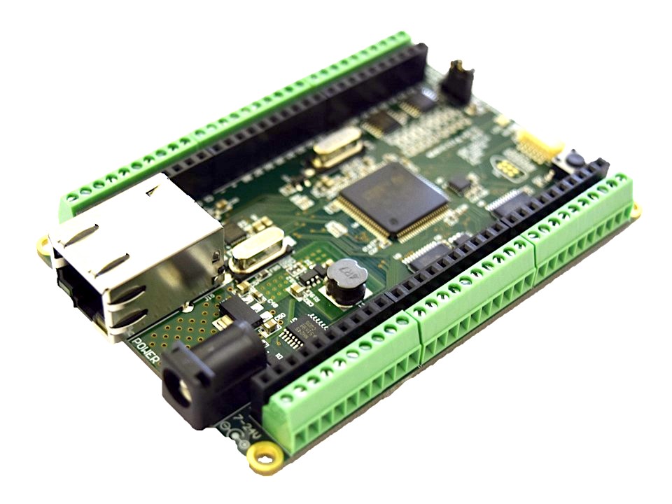
I/O Board
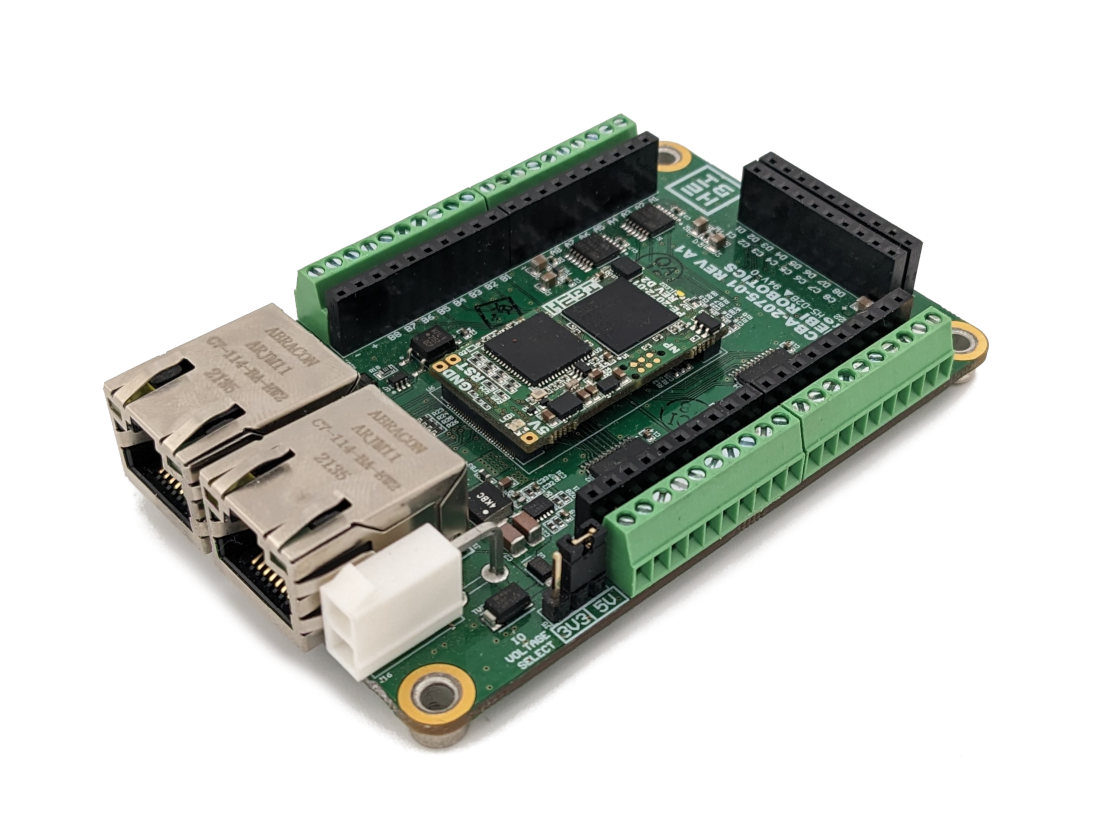
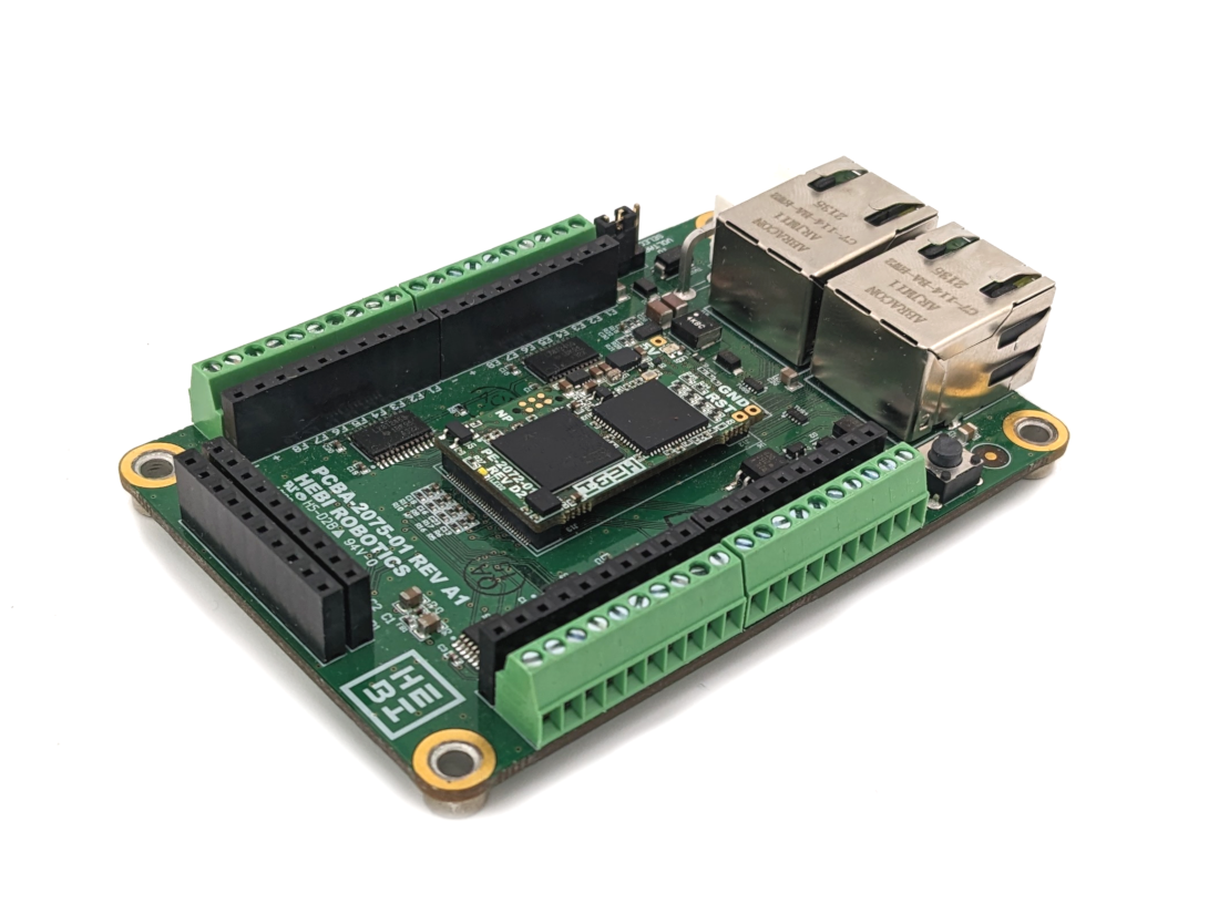
The HEBI I/O Board is an ethernet-enabled module that allows you to easily integrate various low-level sensors into HEBI’s APIs and framework. This module provides general-purpose analog and digital inputs, digital and PWM outputs, encoder inputs, and exposes in the various HEBI APIs in a way that is syncronized with any other modules on the network. It also includes an IMU and on-board orientation estimate, using the same API format as the X-Series actuator.
Some example uses of the I/O Board:
-
Reading analog load cells / pressure sensors
-
Reading signals from limit switches
-
Reading input from buttons / potentiometers
-
Reading quadrature encoders
-
Controlling pneumatic valves (requires external relays)
-
Controlling solenoids (requires external relays)
-
Controlling LED lights
-
Sending digital line signals to other devices
Revisions
| Part Number | Description and Downloads | Image |
|---|---|---|
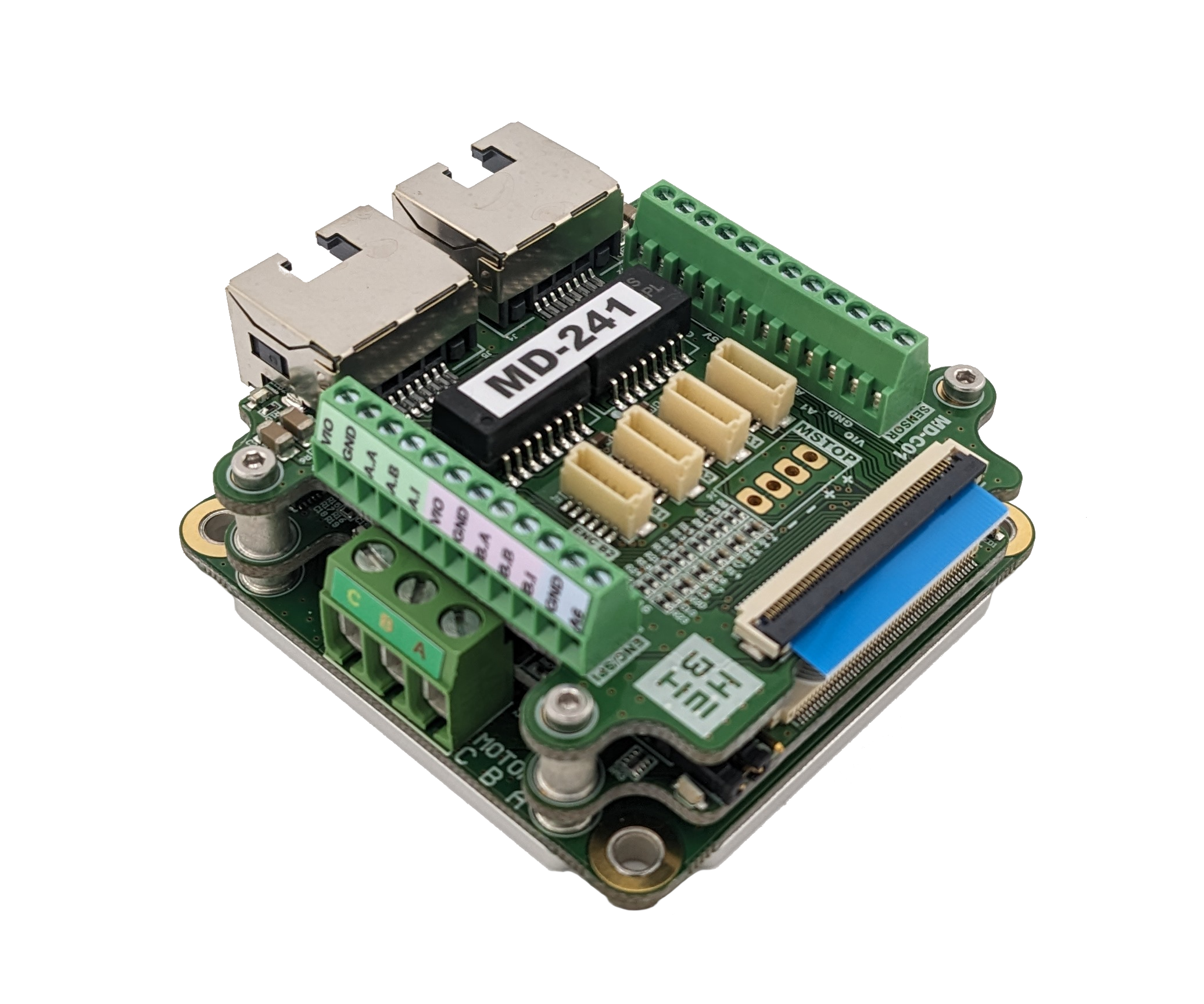
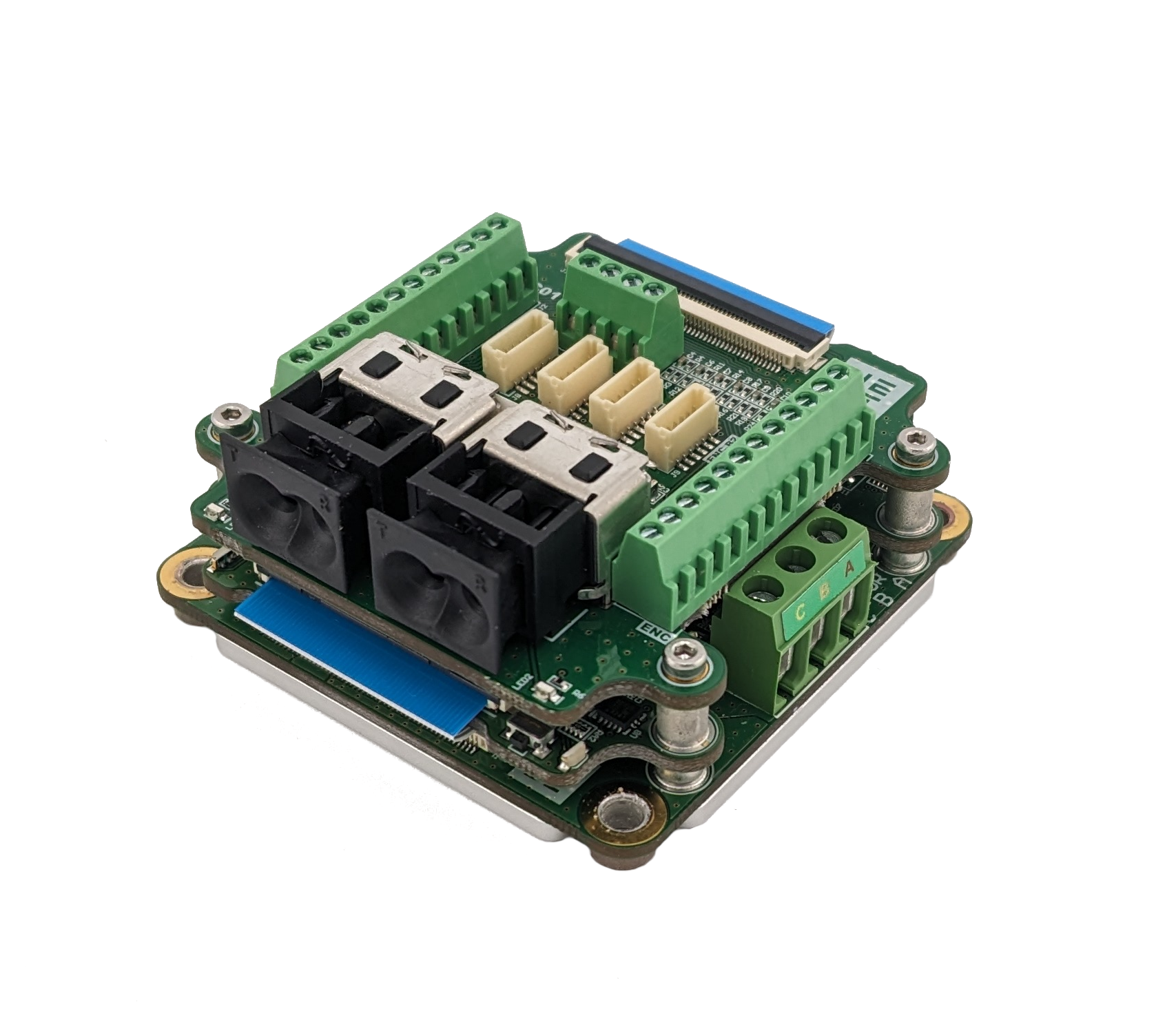
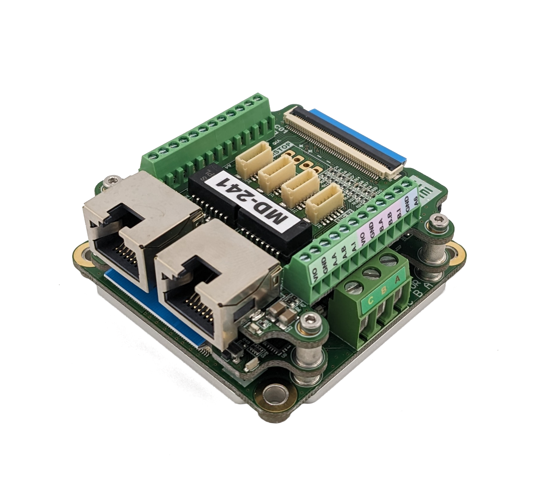
A-2432-01 |
HEBI I/O Board (rev A) |
|
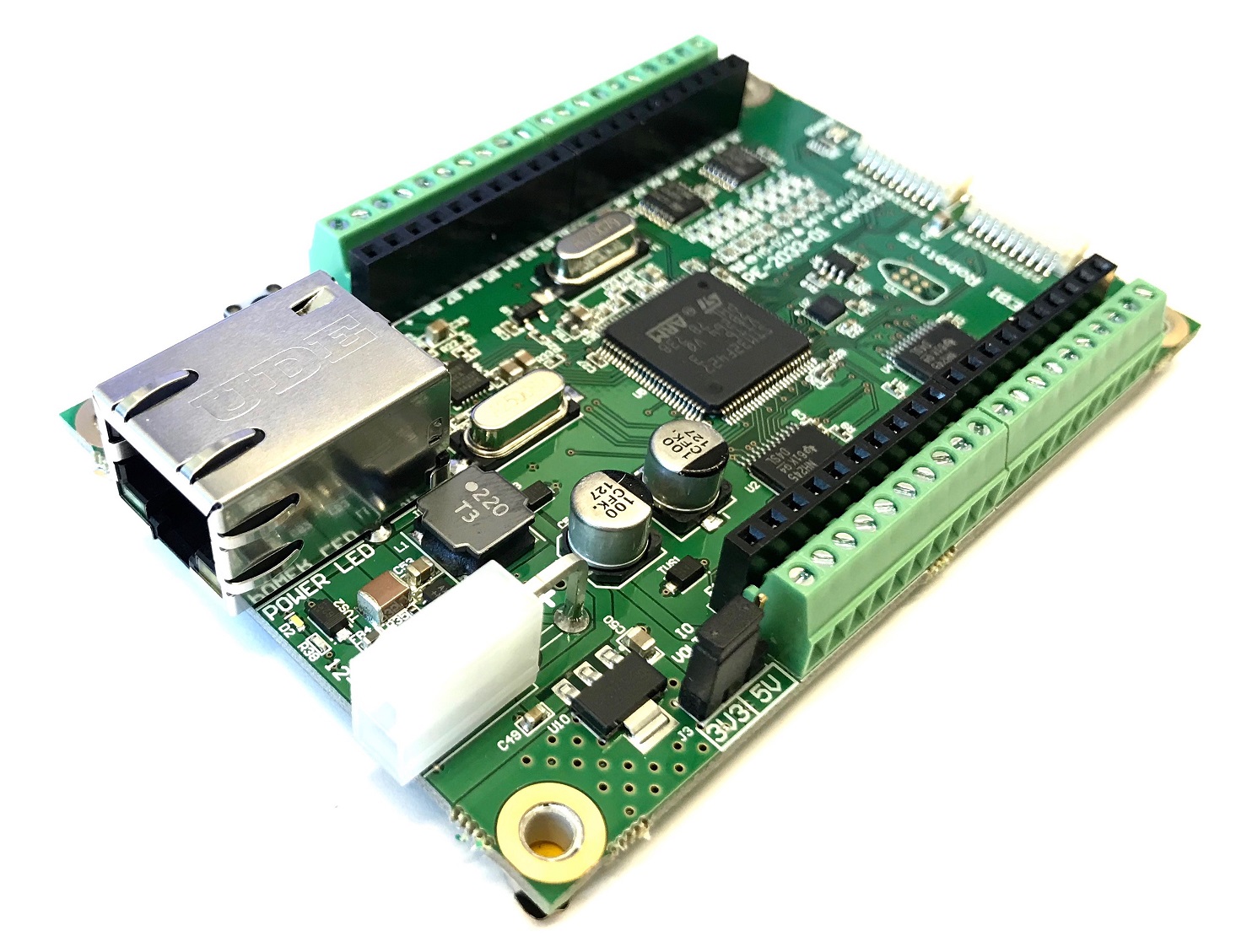
A-2116-02 |
Legacy HEBI I/O Board (rev C) |
|
A-2116-01 |
Legacy HEBI I/O Board (rev B) |
|
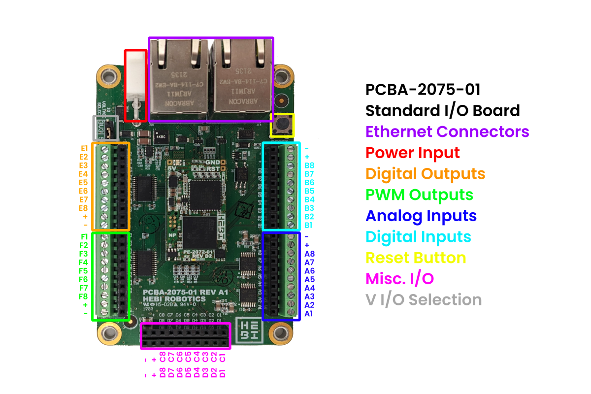
A-2432-01 Interface
The I/O pins described below can be accessed through the HEBI API with I/O Commands / Feedback.
The following specifications only apply to A-2432-01 I/O boards. Contact HEBI Robotics for more details about older revisions.
| Interface | Rating | Description |
|---|---|---|
Power Input |
12V - 48V |
This input uses a 2-pin Molex Minifit connector to receive power. It has a reverse voltage protection diode to prevent damage if the connector is miswired. Care should be taken to avoid high voltage transients at this connector. |
V I/O Selection Header |
3.3V / 5V |
This header is used to switch the output voltage between 3.3V and 5V. Do not move this jumper while the device is powered on. This jumper must be populated for the board to function. |
Reset Button |
This is the hardware reset button for the onboard I/O Micro. |
|
Digital Outputs |
0V / V I/O |
All digital outputs are buffered with one 8-channel SN74LVC8T245 translation transciever. These outputs are capable of 32mA each in 5V mode or 24mA in 3.3V mode. Do not exceed 100mA total on all digital outputs. Refer to the buffer datasheet for more details. |
Digital Inputs |
0V / V I/O |
Please note that all of the digital inputs are connected directly to the onboard I/O Micro. The I/O Micro runs at 3.3V, but it has 5V tolerant inputs. The inputs are not 5V tolerant when the power is disconnected however, so it is important that external 5V sensors be either powered by this board or incorporate a switching (or level shifting) circuit. |
Analog Inputs |
0V - 5V |
All analog inputs have a range of 0-5V, and have a fixed, first order low pass filter with a cutoff frequency of approximately 4.8kHz. The analog resolution is 12 bits. All of the analog inputs are buffered with TSV324IPT op amps. It is recommended that an external calibration procedure is used for high-accuracy applications. |
PWM Outputs |
0V - V I/O |
By default, the PWM outputs are configured to switch at approximately 20kHz. This frequency is good for DC motor control and basic DAC applications. The PWM timer resolution is 10 bits. All PWM outputs are buffered with one 8-channel SN74LVC8T245 translation transciever. These outputs are capable of 32mA each in 5V mode or 24mA in 3.3V mode. Do not exceed 100mA total on all digital outputs. Refer to the buffer datasheet for more details. |
Misc. I/O |
0V - V I/O |
Additional connections for use with customized firmware. See I/O Micro Pinout for more details. |
Additional Specifications
Power & Thermal Considerations
The HEBI I/O Board is rated to a maximum of 300mA from the I/O voltage supplies. Exceeding this current rating may cause the board to malfunction.
The I/O Micro on this board should be heat sunk when this board is assembled into an enclosure. If the electronics are allowed to heat up above 85C the board will stop responding to Ethernet. An onboard temperature sensor can be used to track the temperature of the processor and Ethernet interface.
Data Registers
All data registers updated at a 1kHz interval, so polling the board faster will not produce any benefit.
ESD Precautions
Although there are no overly sensitive components on the I/O Board, there is also no ESD protection. Care must be taken to not damage the device through ESD by taking the appropriate precautions.
General Precautions
The HEBI I/O Board consists of a bare PCB without an enclosure. Care must be taken to protect the connections on the bottom of the PCB. Do not operate the board while it is resting on a conductive surface. Always double check wiring before powering on the board. Never make connections while power is on.
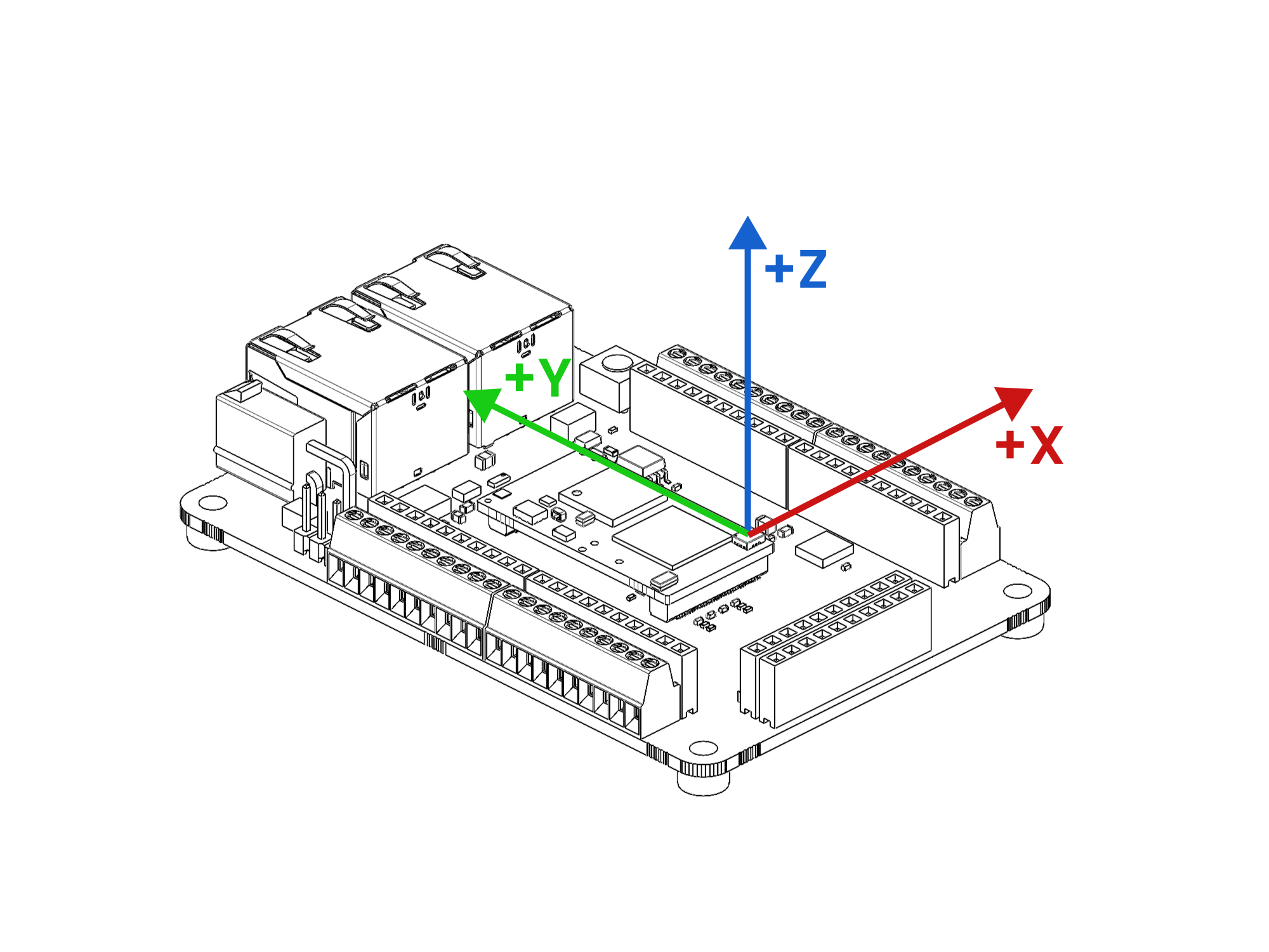
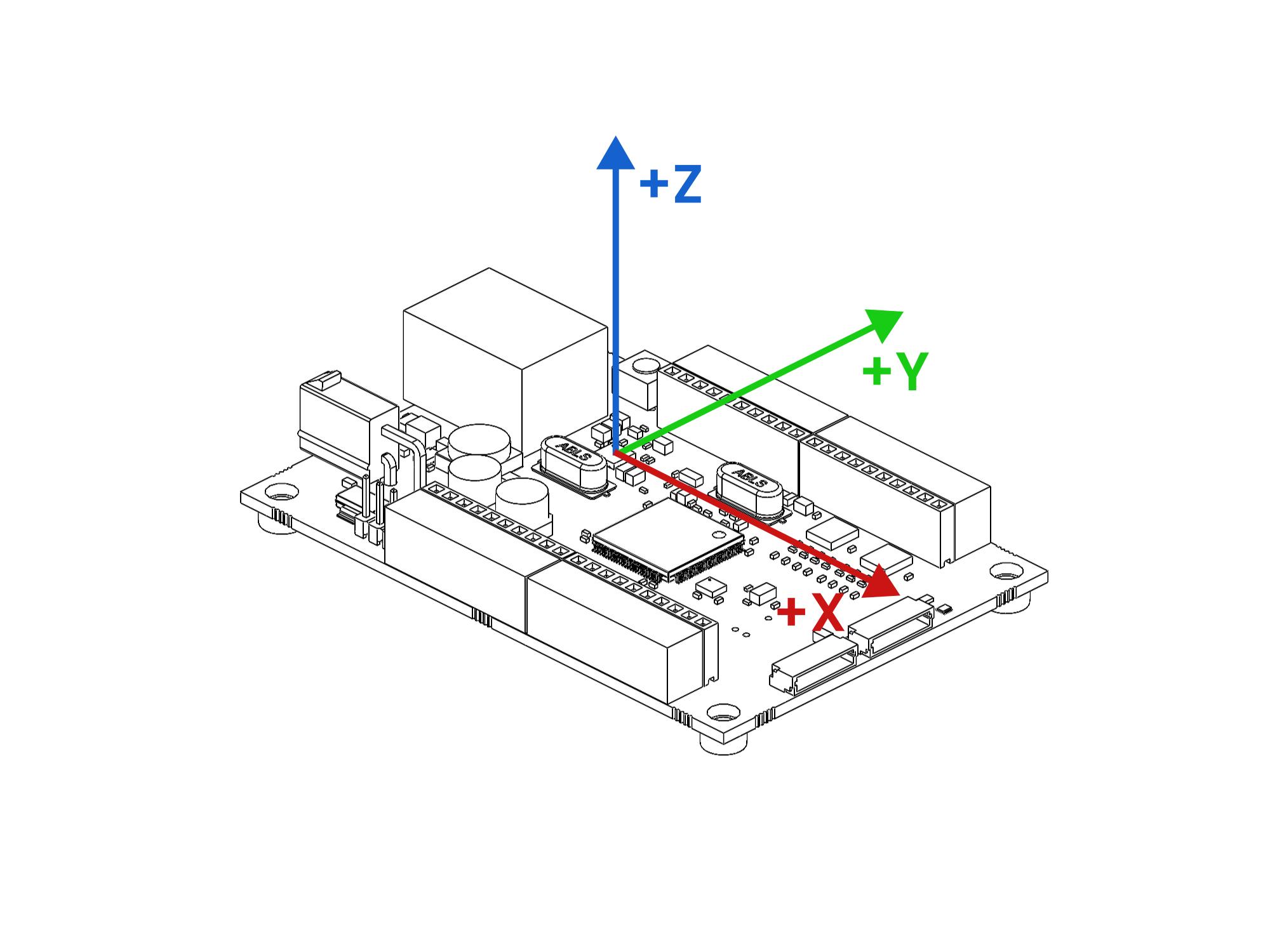
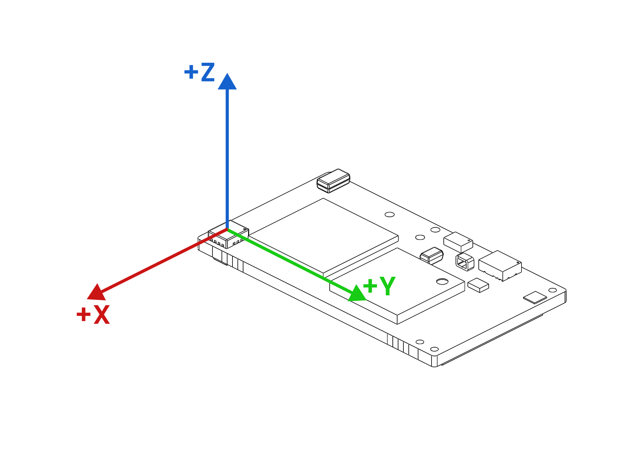
Reference Frame
The reference frame for the I/O board’s IMU (accelerometer, gyro, orientation) is shown in the image below. The origin of the coordinate frame is shown centered on the IMU.
I/O Utility Board
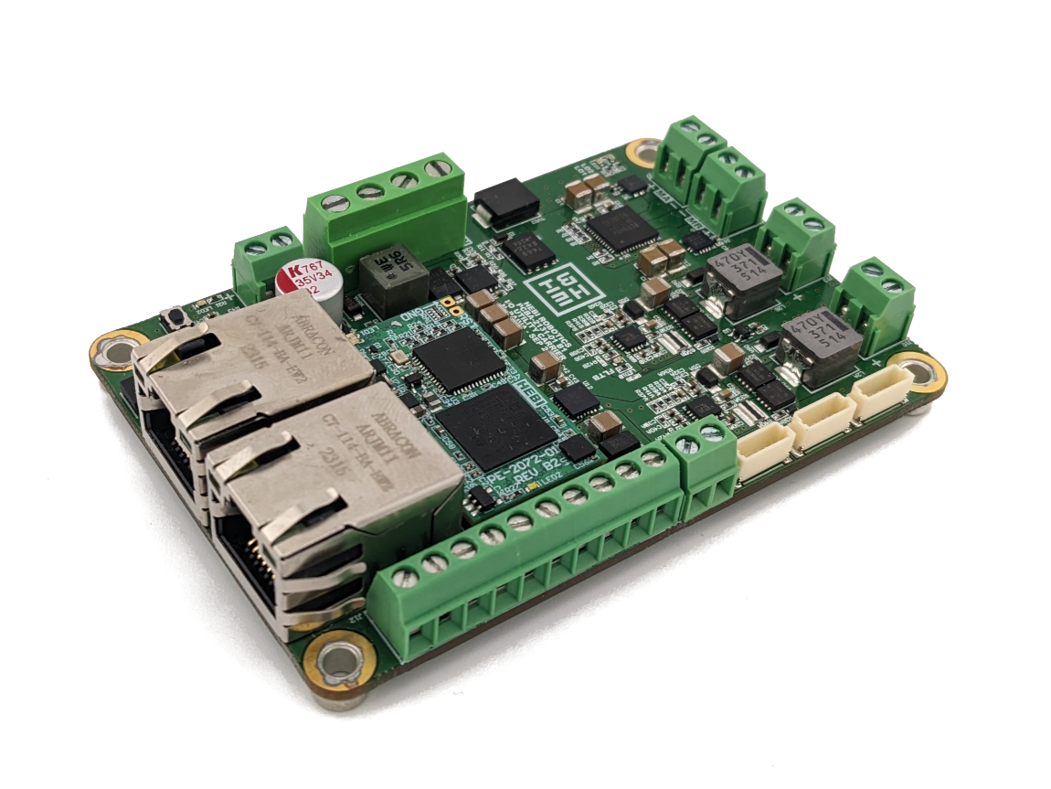
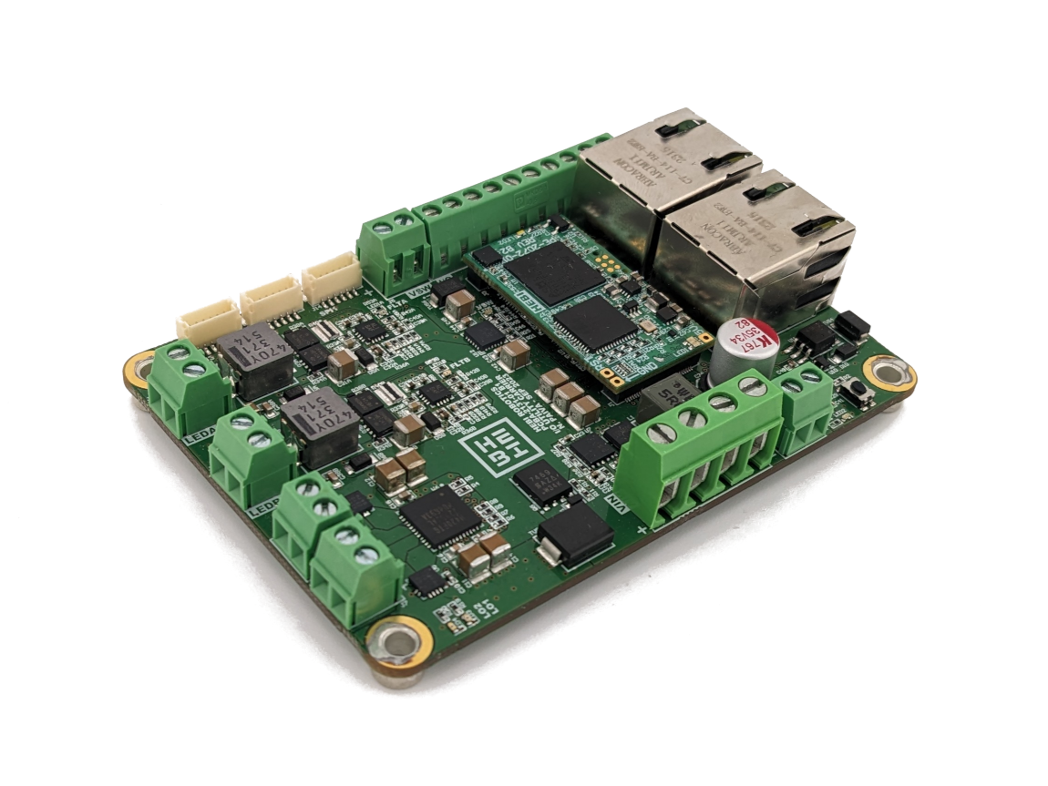
The HEBI I/O Utility Board is a high-powered version of the traditional I/O Board. This Board allows you to control up to 2 independent LED outputs, 2 independent DC motor outputs, and a high power FET output. A beefy 5V output puts out enough juice to let you run a Raspberry Pi!
It has everything but the kitchen sink!
Features
-
2 Ethernet Ports for Ethernet Passthrough
-
Terminal Blocks for All Main Connectors
-
Same size / bolt pattern as the Standard I/O Board
-
High power 5V output
-
2 x LED Drivers
-
Dual Channel H-Bridge Motor Driver
-
Bus power output
Revisions
| Part Number | Description and Downloads | Image |
|---|---|---|
A-2545-01 |
HEBI I/O Utility Board (Using I/O Micro) |
|
Interface
The I/O pins described below can be accessed through the HEBI API with I/O Commands / Feedback.
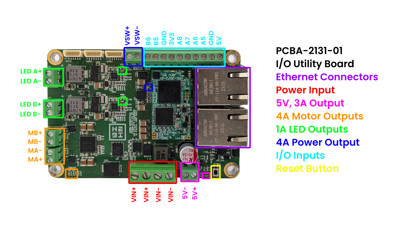
| Interface | Rating | Description |
|---|---|---|
Power Input |
25V - 42V |
This input is used to provide power to the board. This board is designed to run off of a 10S Lithium Ion Battery. |
Main 5V Output |
5V, 3A |
This output is designed for a 15W output (Enough to drive a RPi4). It is internally limited to 3.75A with a LS0505EVD22 eFuse chip. A status LED indicates when this interface is enabled. |
Motor Output |
4.5A Per Motor |
This connector features a dual-output TB67H420FTG H-Bridge Motor Driver and current sensing provided by a ACS71240 hall effect sensor. LO1 and LO2 are broken out to status LEDs. |
LED Output |
1A Per Channel |
Two independent LED drivers capable of up to 1A each. Fault status LEDs are broken out as well. |
Power Output |
4A Nominal |
A bus voltage output with current limiting provided by a TPS16530RGER chip. |
Reset Button |
This is the hardware reset button for the onboard I/O Micro. |
|
A5-8 |
0V - 5V |
Extra analog inputs. Buffered and low-passed with a cutoff frequency of 4.8kHz. |
B5-6 |
0V - 5V |
Extra digital inputs. |
I/O Power |
Extra power outputs for the misc. I/O. No onboard current limiting. |
I/O Channel Mapping
| I/O Channel | Function |
|---|---|
|
Motor B Current |
|
Motor A Current |
|
LED A Current |
|
LED B Current |
|
Spare Analog Input 1 |
|
Spare Analog Input 2 |
|
Spare Analog Input 3 |
|
Spare Analog Input 4 |
|
TB67H420FTG LO1 |
|
TB67H420FTG LO2 |
|
LED Fault A |
|
LED Fault B |
|
Spare Digital Input 1 |
|
Spare Analog Input 2 |
|
Power Output Fault |
|
Motor B Input 1 |
|
Motor B Input 2 |
|
Motor A Input 1 |
|
Motor A Input 2 |
|
LED Enable A |
|
LED Enable B |
|
Power Output Enable |
|
Motor B PWM |
|
Motor A PWM |
|
LED A PWM |
|
LED B PWM |
Power & Thermal Considerations
The I/O Micro on this board should be heat sunk when this board is assembled into an enclosure. If the electronics are allowed to heat up above 85C the board will stop responding to Ethernet. An onboard temperature sensor can be used to track the temperature of the processor and Ethernet interface.
Data Registers
All data registers updated at a 1kHz interval, so polling the board faster will not produce any benefit.
ESD Precautions
Although there are no overly sensitive components on the I/O Utility Board, there is also no ESD protection. Care must be taken to not damage the device through ESD by taking the appropriate precautions.
General Precautions
The HEBI I/O Utility Board consists of a bare PCB without an enclosure. Care must be taken to protect the connections on the bottom of the PCB. Do not operate the board while it is resting on a conductive surface. Always double check wiring before powering on the board. Never make connections while power is on.
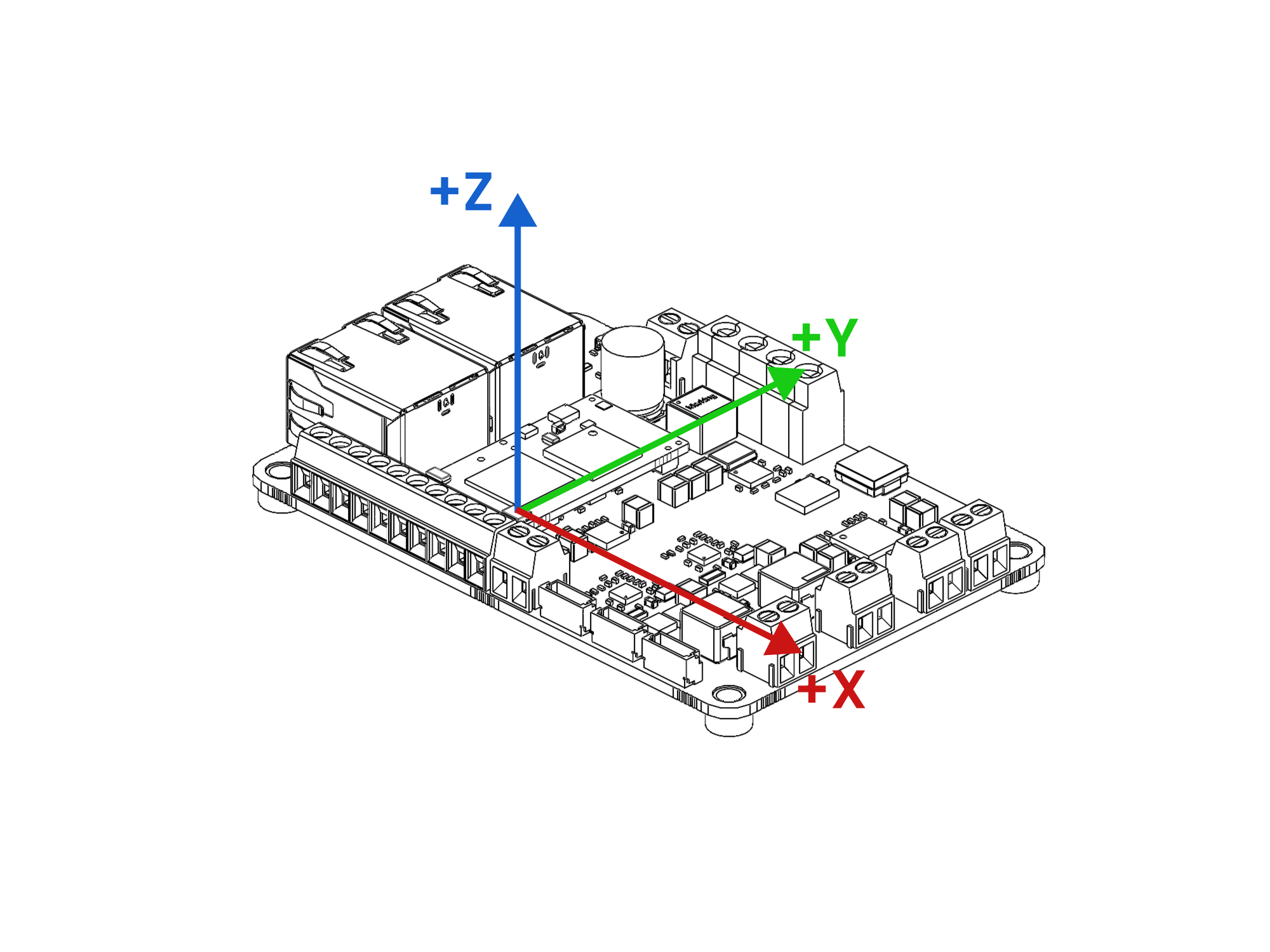
Reference Frame
The reference frame for the I/O board’s IMU (accelerometer, gyro, orientation) is shown in the image below. The origin of the coordinate frame is shown centered on the IMU.
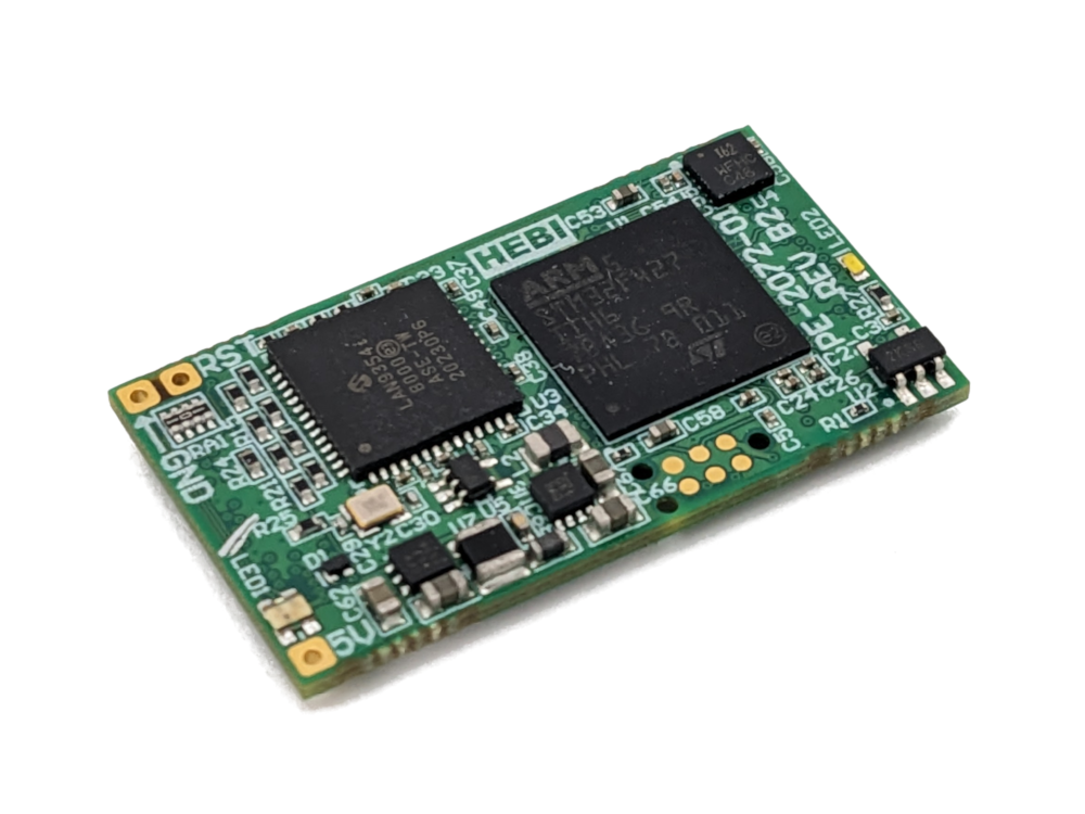
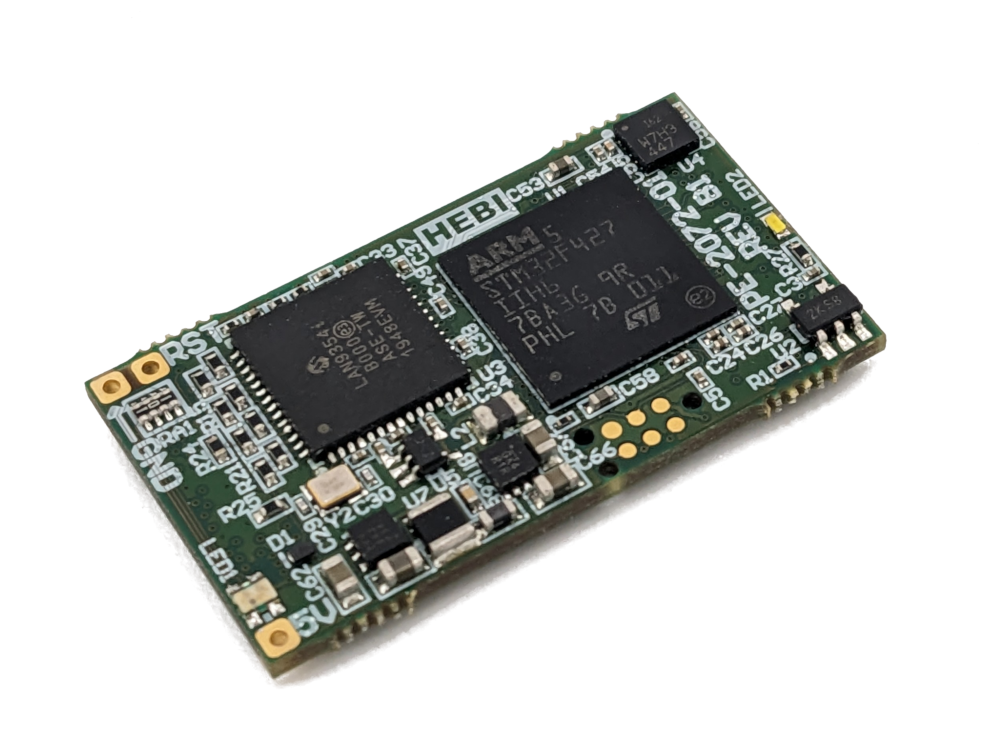
I/O Micro
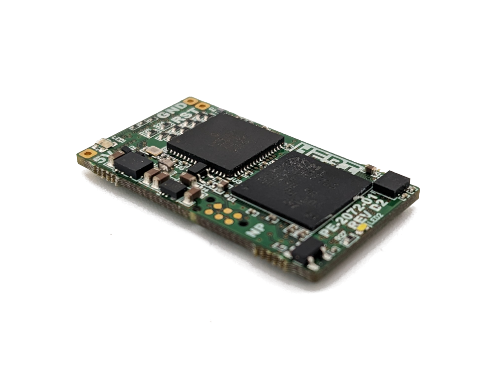
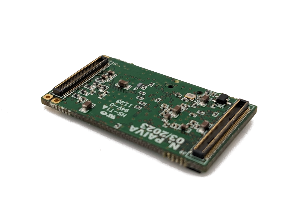
The HEBI I/O Micro is the core of every I/O Board. It has all of the circuitry and firmware required to interface with HEBI APIs in a tiny package. A flexible onboard Ethernet switch lets this board interface with both Fiber and Copper Ethernet.
The I/O Micro enables the creation of purpose-built I/O boards for any application!
Features
-
The smallest I/O Board!
-
100% Rectangular!
-
32mm x 18mm x 5mm board footprint
-
Built in 100Mbit Ethernet Switch
-
2 Ports with built-in Ethernet PHYs
-
Each Port Capable of either Fiber or Copper Ethernet
-
-
Low profile, high density DF40 connector interface
-
Runs off of a 2W power supply of either 5V or 3.3V
-
Onboard IMU
-
Integrated Status LED
Revisions
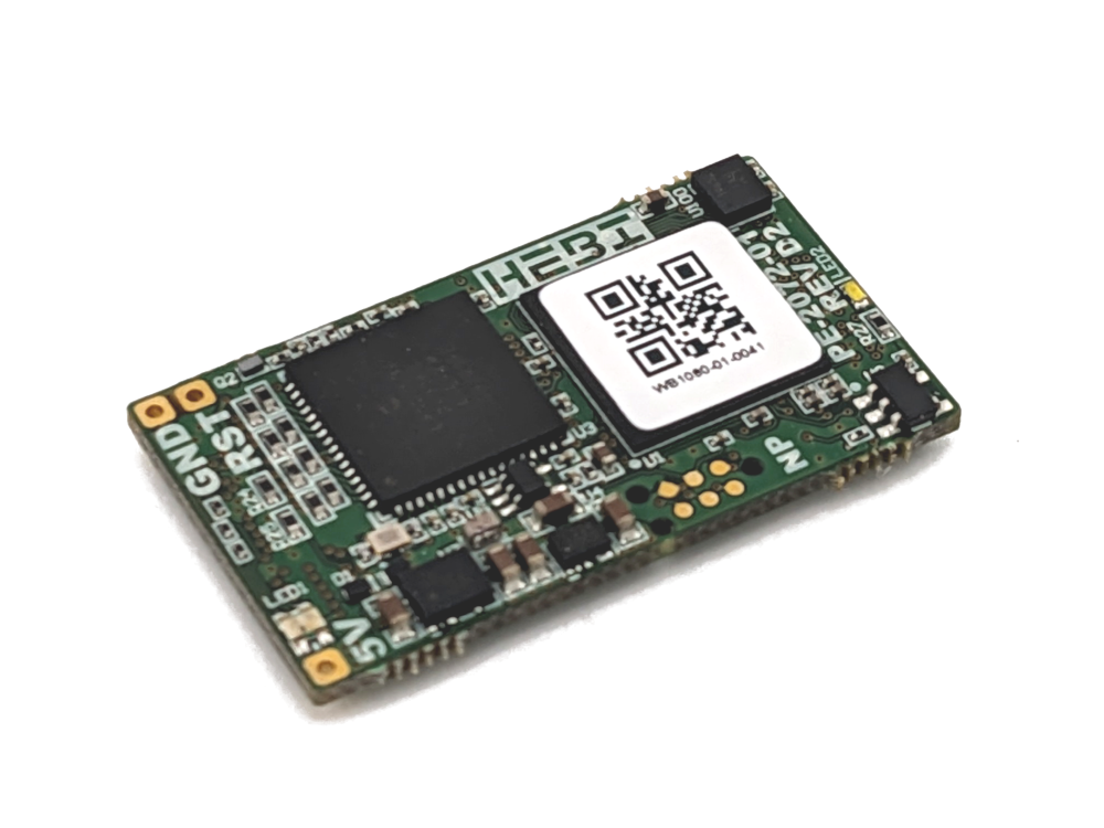
| Part Number | Description and Downloads | Image |
|---|---|---|
PCBA-2072-01 D2 |
I/O Micro (rev D) |
|
PCBA-2072-01 D1 |
I/O Micro (rev D) |
|
PCBA-2072-01 B2 |
I/O Micro (rev B) |
|
PCBA-2072-01 B1 |
I/O Micro (rev B) |
|
Pinout
The I/O Micro has all of the connections available on the regular I/O board. Additional connections are available with custom HEBI firmware.
The I/O pins described below can be accessed through the HEBI API with I/O Commands / Feedback.
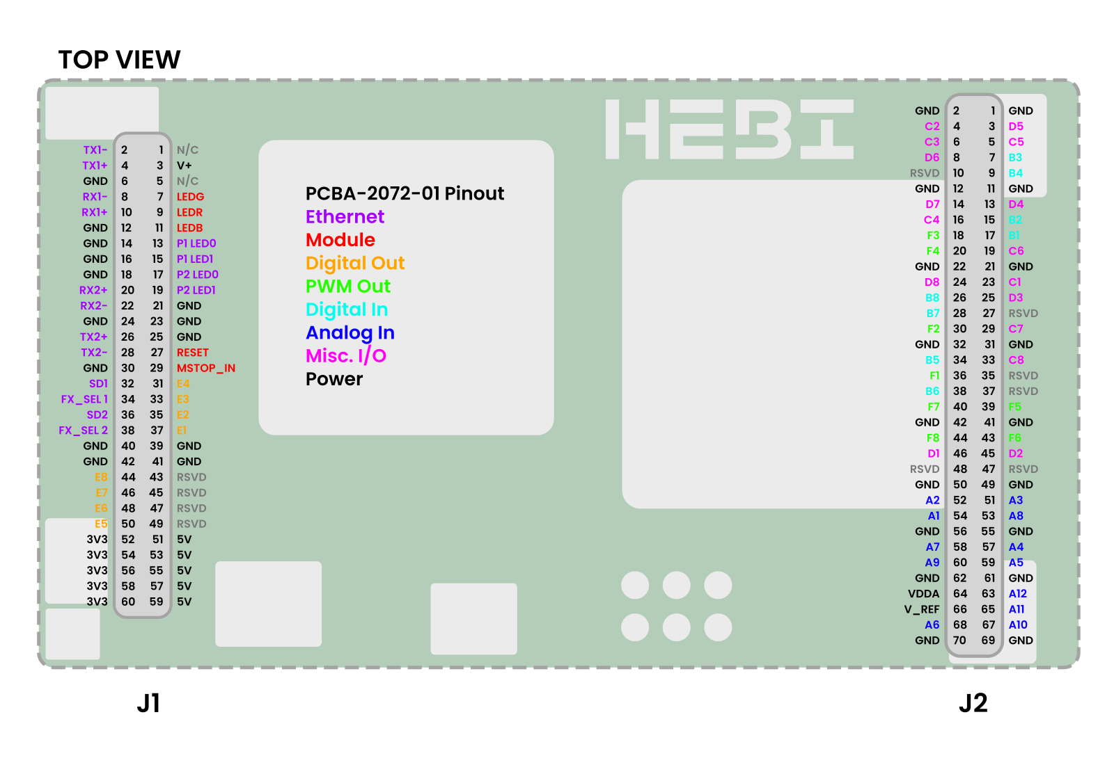
I/O Pins
| Connector | Pin | API Name | Function |
|---|---|---|---|
J1 |
37 |
E1 |
Digital Output 1 |
J1 |
35 |
E2 |
Digital Output 2 |
J1 |
33 |
E3 |
Digital Output 3 |
J1 |
31 |
E4 |
Digital Output 4 |
J1 |
50 |
E5 |
Digital Output 5 |
J1 |
48 |
E6 |
Digital Output 6 |
J1 |
46 |
E7 |
Digital Output 7 |
J1 |
44 |
E8 |
Digital Output 8 |
J2 |
54 |
A1 |
Analog Input 1 |
J2 |
52 |
A2 |
Analog Input 2 |
J2 |
51 |
A3 |
Analog Input 3 |
J2 |
57 |
A4 |
Analog Input 4 |
J2 |
59 |
A5 |
Analog Input 5 |
J2 |
68 |
A6 |
Analog Input 6 |
J2 |
58 |
A7 |
Analog Input 7 |
J2 |
53 |
A8 |
Analog Input 8 |
J2 |
60 |
A9 |
Analog Input 9 Custom Firmware Required |
J2 |
67 |
A10 |
Analog Input 10 Custom Firmware Required |
J2 |
65 |
A7 |
Analog Input 11 Custom Firmware Required |
J2 |
63 |
A8 |
Analog Input 12 Custom Firmware Required |
J2 |
36 |
F1 |
PWM Output 1 |
J2 |
30 |
F2 |
PWM Output 2 |
J2 |
18 |
F3 |
PWM Output 3 |
J2 |
20 |
F4 |
PWM Output 4 |
J2 |
39 |
F5 |
PWM Output 5 |
J2 |
43 |
F6 |
PWM Output 6 |
J2 |
40 |
F7 |
PWM Output 7 |
J2 |
44 |
F8 |
PWM Output 8 |
J2 |
17 |
B1 |
Digital Input 1 |
J2 |
15 |
B2 |
Digital Input 2 |
J2 |
7 |
B3 |
Digital Input 3 |
J2 |
9 |
B4 |
Digital Input 4 |
J2 |
34 |
B5 |
Digital Input 5 |
J2 |
38 |
B6 |
Digital Input 6 |
J2 |
28 |
B7 |
Digital Input 7 |
J2 |
26 |
B8 |
Digital Input 8 |
J2 |
23 |
C1 |
Quad Encoder 1 A |
J2 |
4 |
C2 |
Quad Encoder 1 B |
J2 |
6 |
C3 |
Quad Encoder 1 I |
J2 |
16 |
C4 |
Quad Encoder 2 A |
J2 |
5 |
C5 |
Quad Encoder 2 B |
J2 |
19 |
C6 |
Quad Encoder 2 I |
J2 |
29 |
C7 |
UART 1 RX Custom Firmware Required |
J2 |
33 |
C8 |
UART 1 TX Custom Firmware Required |
J2 |
46 |
D1 |
UART 2 RX Custom Firmware Required |
J2 |
45 |
D2 |
UART 2 TX Custom Firmware Required |
J2 |
25 |
D3 |
I2C SCL Custom Firmware Required |
J2 |
13 |
D4 |
I2C SDA Custom Firmware Required |
J2 |
3 |
D5 |
SPI MISO Custom Firmware Required |
J2 |
8 |
D6 |
SPI MOSI Custom Firmware Required |
J2 |
14 |
D7 |
SPI SCK Custom Firmware Required |
J2 |
24 |
D8 |
SPI CS Custom Firmware Required |
Other Pins
| Connector | Pin | Name | Function |
|---|---|---|---|
J1 |
3 |
V+ |
Voltage Sense Input [48V max] (Optional, but Recommended Functionality) |
J1 |
7 |
LEDG |
RGB LED Green Output [Active High] (Should be buffered if used for external LED) |
J1 |
9 |
LEDR |
RGB LED Red Output [Active High] (Should be buffered if used for external LED) |
J1 |
11 |
LEDB |
RGB LED Blue Output [Active High] (Should be buffered if used for external LED) |
J1 |
27 |
RESET |
Hardware Reset Button Input [Active Low] (Onboard Pullup) |
J1 |
29 |
MSTOP_IN |
MSTOP Input (External Circuitry Required) |
J1 |
2 |
TX1- |
Negative Diff. Pair Connection for Ethernet Port 1 TX |
J1 |
4 |
TX1+ |
Positive Diff. Pair Connection for Ethernet Port 1 TX |
J1 |
8 |
RX1- |
Negative Diff. Pair Connection for Ethernet Port 1 RX |
J1 |
10 |
RX1+ |
Positive Diff. Pair Connection for Ethernet Port 1 RX |
J1 |
32 |
SD1 |
Signal Detect input for Fiber Mode for Eth. Port 1 |
J1 |
34 |
FX_SEL 1 |
Fiber / Copper Mode Select for Eth. Port 1 |
J1 |
13 |
P1 LED0 |
Link / Activity Indicator for Eth. Port 1 |
J1 |
15 |
P1 LED1 |
Speed Indicator for Eth. Port 1 |
J1 |
28 |
TX2- |
Negative Diff. Pair Connection for Ethernet Port 2 TX |
J1 |
26 |
TX2+ |
Positive Diff. Pair Connection for Ethernet Port 2 TX |
J1 |
22 |
RX2- |
Negative Diff. Pair Connection for Ethernet Port 2 RX |
J1 |
20 |
RX2+ |
Positive Diff. Pair Connection for Ethernet Port 2 RX |
J1 |
36 |
SD2 |
Signal Detect input for Fiber Mode for Eth. Port 2 |
J1 |
38 |
FX_SEL 2 |
Fiber / Copper Mode Select for Eth. Port 2 |
J1 |
17 |
P1 LED0 |
Link / Activity Indicator for Eth. Port 2 |
J1 |
19 |
P1 LED1 |
Speed Indicator for Eth. Port 2 |
J1 |
51, 53, 55, 57, 59 |
5V |
5V Power Supply Input |
J1 |
52, 54, 56, 58, 60 |
3V3 |
3.3V Power Supply Output (or input when bypassing 5V regulator) |
J2 |
64 |
VDDA |
Analog Voltage Supply Output (Reference Only) |
J2 |
66 |
V_REF |
ADC Reference Voltage Output |
J1 |
6, 12, 14, 16, 18, 21, 23, 24, 25, 30, 39, 40, 41, 42 |
GND |
Ground Connection |
J2 |
1, 2, 11, 12, 21, 22, 31, 32, 41, 42, 49, 50, 55, 56, 61, 62, 69, 70 |
GND |
Ground Connection |
J1 |
1,5 |
N/C |
Unused |
J1 |
43,45,47,49 |
RSVD |
Additional reserved I/O Pins |
J2 |
10, 27, 35, 37, 47, 48 |
RSVD |
Additional reserved I/O Pins |
Additional Specifications
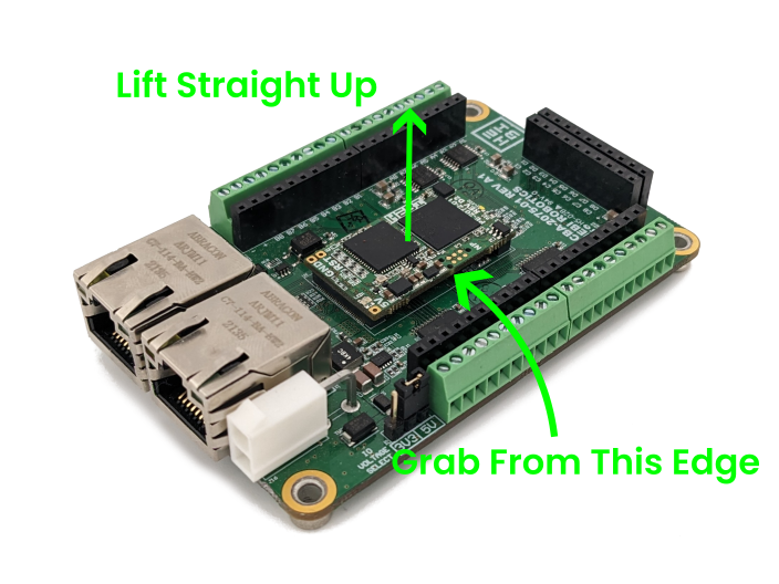
Connector Precautions
The DF40 connectors on the bottom of the board are fragile. Take care to remove the I/O Micro such that it is as parallel to its carrier board as possible. If it cannot be removed easily, the best way to remove it is to lift it gently, one side at a time, on the long edge. This will allow you to dislodge the board to board connectors with lower risk of damage.
Power & Thermal Considerations
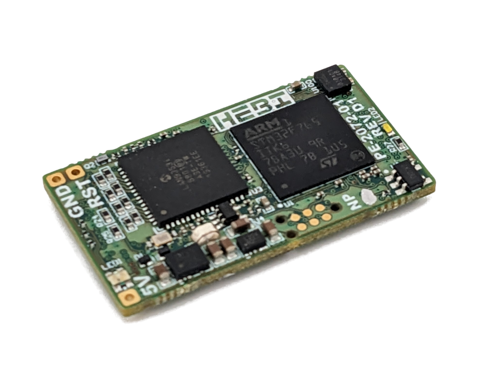
The I/O Micro has onboard 5V → 3.3V and 3.3V → 1.2V DC/DC converters to provide the various voltage rails required for its circuitry. The 5V input and the 3.3V output are exposed to the connector. The 1.2V supply is internal to the board. The 3.3V DC/DC is designed with enough headroom to run peripheral circuitry. Typical usage should be kept under 300mA when the DC/DC converters on the board do not have a good heat sink.
The two chips on board that consume the most power are the LAN9353 and the STM32F7. The LAN9353 has a worst case power draw of ~560mW and the STM32F7 has a worst case power draw of ~900mW. When no other peripherals are used the I/O Micro can be powered with a minimum 2W supply. It is recommended to power the I/O Micro with a 5V, 1A supply to provide sufficient power for the I/O Micro itself as well as any peripheral circuitry. Ensure a good connection to the Ground and 5V pins of the I/O Micro.
The I/O Micro should be heat sunk when assembled into an enclosure. If the electronics are allowed to heat up above 85C the board will stop responding to Ethernet. An onboard temperature sensor can be used to track the temperature of the processor and Ethernet interface.
ESD Precautions
The I/O Micro does not have any additional ESD protection built in. All pins are directly connected to a pin on the onboard Microcontroller or Ethernet Switch. Take appropriate precautions to avoid damaging the device through ESD.
General Precautions
The I/O Micro consists of a bare PCB without an enclosure. Care must be taken to protect the board from mechanical damage. Do not remove the I/O micro from its carrier board while the board is powered on.
Reference Frame
The reference frame for the I/O Micro’s IMU (accelerometer, gyro, orientation) is shown in the image below. The origin of the coordinate frame is shown centered on the IMU.
I/O Board Feedback
| Parameter | Units | Description |
|---|---|---|
|
|
The current time from the system clock used by the API. This is a single value that corresponds to all feedback at this timestep. |
|
|
The system time when feedback was received by each module. The most recent of these times is what is reported as the single |
|
|
The system time when feedback requests were sent to each module. |
|
|
The hardware timestamp when each module in the group transmitted its feedback. Time initializes at 0 when a module is powered on. |
|
|
The hardware timestamp when each module in the group received a request for feedback. Time initializes at 0 when a module is powered on. |
|
|
8 analog inputs, with a range of 0-5V. |
|
|
8 digital inputs, which can handle either 3.3V or 5V levels. |
|
|
Quadrature encoder input. |
|
|
Quadrature encoder input. |
|
|
The currently commanded values on the 8 digital outputs. |
|
|
The currently commanded values on the 8 PWM outputs. |
|
|
A module’s sensed 3-DoF acceleration from an internal IMU, including gravity. Depending on the API, XYZ values are combined together into a single vector or returned individually. |
|
|
A module’s sensed 3-DoF angular velocity from an internal IMU. Depending on the API, XYZ values are combined together into a single vector or returned individually. |
|
|
A module’s 3-DoF orientation based on an onboard complementary filter. The heading component of the estimated orientation will drift over time, as the filter uses only accelerometers and gyros. Depending on the API, quaternion components are combined together into a single vector or returned individually. |
|
|
The sensed bus voltage into the module. |
|
|
The sensed temperature of the electronics (IMU) on the IO Micro. |
|
|
The sensed temperature of the processor on the IO Micro. |
|
|
RGB color values of the status LED. |
I/O Commands
| Parameter | Units | Description |
|---|---|---|
|
|
8 digital outputs, which can output either 3.3V or 5V levels. |
|
|
8 PWM outputs, which can output either 3.3V or 5V levels, depending on a jumper setting on the I/O Board. The switching frequency of the PMW outputs is settable, using the "Switching freq" setting field on the Motor Driver Tab in Scope. The "Advanced" view needs to be enabled for this setting to be visible. |
In addition to commands related to I/O a number of other things can be commanded and/or set.
| Parameter | Units | Description |
|---|---|---|
|
|
The desired user-settable name that an actuator shows up as in a |
|
|
The desired user-settable family that an actuator shows up as in a |
|
|
Boots a module from bootloader mode into application mode. |
|
|
Reboots a module. |
|
|
Saves all the settings and gains that are currently set on a module, so that they are loaded after reboot. |
|
|
Override RGB color values of the status LED. |
Motor Driver
The Motor Driver is a beta product and not available for individual sale on our website. Contact HEBI Robotics for more details.
The HEBI Motor Driver is a flexible system intended for driving third party motors with the HEBI API. It’s designed from the ground up to be modular in every way!
The HEBI Motor Driver is a stackup of multiple boards that are designed to be swapped out easily. At its core is an I/O Micro with an integrated IMU and HEBI API functionality. The interface board on the top allows the Motor Driver to function with either Copper or Fiber Ethernet. The interface board can be customized for maximum flexibility!
Features:
-
Flexible input voltage (15-50V)
-
500W continuous power rating at 36-50V
-
1000W peak power rating at 36-50V
-
Small Package: 60mm x 65mm x 25mm
-
Integrated Heat Spreader
-
Integrated IMU
-
100 Mbps Ethernet, available in either Copper or Fiber interfaces
-
Flexible I/O inputs
-
Onboard I/O Voltage Supply (Selectable 5V / 3.3V, 300mA)
-
6 Analog inputs
-
Up to 4 SPI Encoders or 2 Quadrature Encoders
-
On/Off Board Temperature Sensoprs
-
Hall Sensor inputs
-
Rich feedback on input/output voltage and current
-
Integrated MSTOP inputs
-
-
Auxiliary output
-
Used for driving brake solenoids or shunt regulators
-
Rated to 2A continuous in inductive loads
-
Rated to 10A continuous in resistive loads
-
Available Configurations
| Part Number | Description and Downloads | Image |
|---|---|---|
A-2433-01 |
MD-A Motor Driver with Copper Ethernet (rev C) |
|
A-2433-02 |
MD-AF Motor Driver with Fiber Ethernet (rev C) |
|
Physical Interface
The Motor Driver has connectors and LEDs on nearly every side to minimize the footprint of the device. The most important components are explained below.
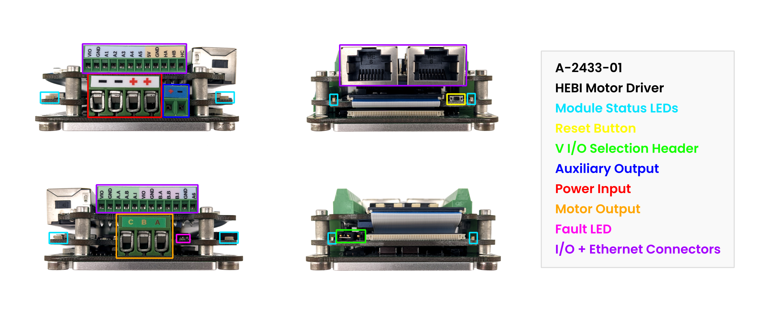
| Interface | Description |
|---|---|
Status LEDs |
The Status LEDs implement all standard module status codes as well as a few Motor Driver specific status codes listed below. |
I/O Inputs |
These terminal blocks provide the interface for the various analog, encoder, and hall sensor inputs. |
Reset Button |
This is the hardware reset button |
Motor Inputs |
The windings of a 3 phase motor are connected to the motor driver here. |
Power Inputs |
Power (and optional capacitors) are connected to the motor driver here. |
V I/O Selection Header |
This header allows for VIO to be switched between 3.3V and 5V. |
Fault LED |
This LED will turn on when a hardware fault has occured. This LED should not light up in normal usage. |
Additional Status LED Codes
| LED Pattern | Meaning |
|---|---|
Green Blink |
Relative encoder not initialized yet. |
Red Fade |
Module safety fault. |
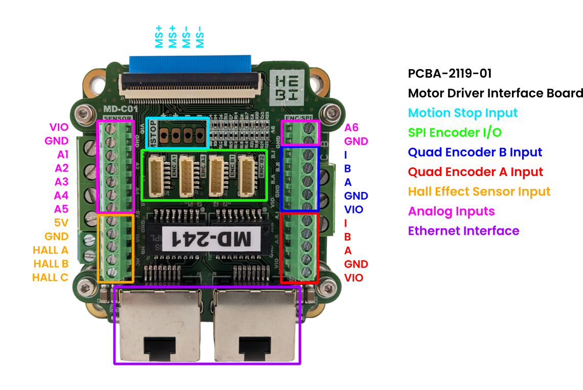
Interface Configuration
The Motor Driver is designed with a replaceable interface board that allows for easy swapping of connectors. The base configuration features connections for Hall Effect Sensors, up to 4 SPI encoders, up to 2 quadrature encoders, and 6 Analog Inputs.
Example Encoder Configuration Matrix
There are four possible encoder ports on the Motor Driver, subdivided into two groups (A, B). You can run up to two SPI encoders per group or one Quadrature encoder per group. Quadrature encoders cannot be run on the same group as a SPI encoder - they use the same electrical interface.
| Port Group | Sub Port | Ex. Config 1 | Ex. Config 2 | Ex. Config 3 | Ex. Config 4 | Ex. Config 5 |
|---|---|---|---|---|---|---|
A |
1 |
SPI |
QUAD |
SPI |
QUAD |
X |
2 |
X |
SPI |
X |
|||
B |
1 |
SPI |
X |
SPI |
QUAD |
QUAD |
2 |
X |
SPI |
SPI |
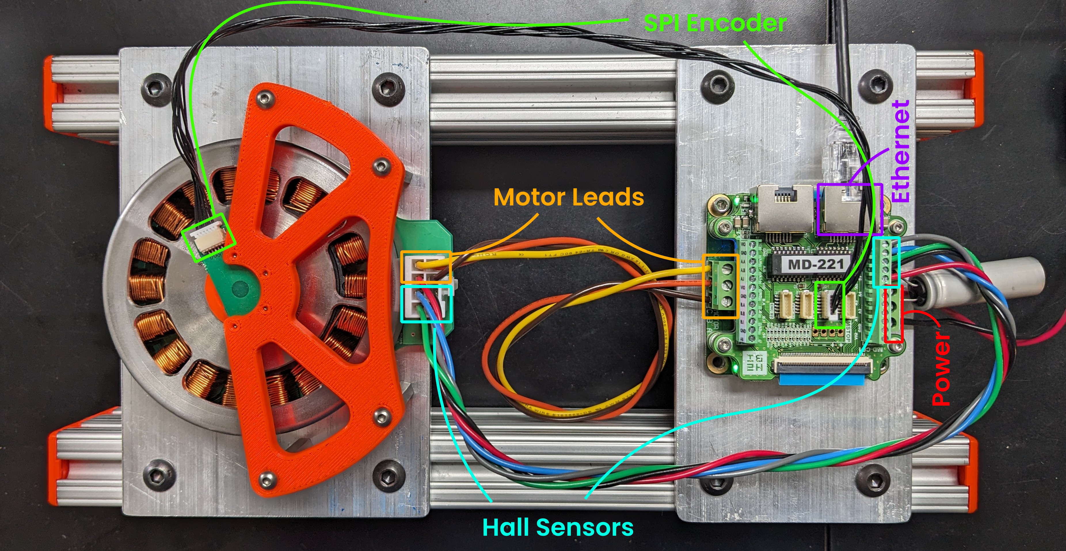
Basic Wiring
The Motor Driver uses terminal blocks for most inputs to maximize wiring flexibility. At a bare minimum, you will need to connect the following for every motor:
-
3 Phase Motor Winding Leads
-
15-48V DC Power Input
-
Ethernet Connection to a Computer
-
Motor Encoder
-
Hall Effect Sensors (For Block Commutation)
-
Quad / SPI Encoder (For FOC)
-
The base configuration has ~135 uF of ceramic capacitors on board connected to the main power input. For certain high power motors or high-impedance power supplies, you may need additonal bulk capacitance (shown below).
Example Wiring of a Maxon EC90 Motor with a SPI AS5047U Encoder for FOC Operation
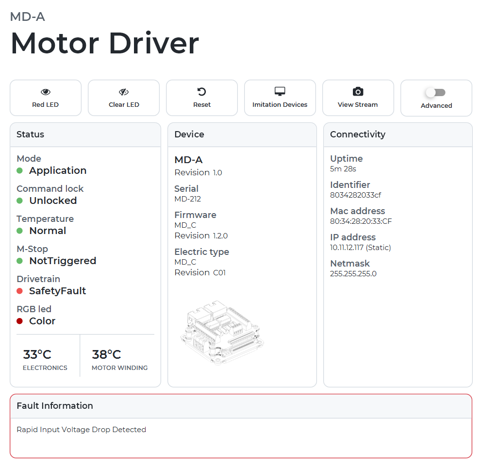
Fault Handling
In typical use cases, the LED status codes will match the codes defined here: LED Status Codes.
In the event of a safety fault the Motor Driver LEDs will slowly fade the color red on and off. This will be reflected in the Dashboard tab of Scope in the Status box. The Drivetrain status will show up as "SafetyFault". Additionally, a verbose description of the fault will be displayed in the "Fault Information" box at the bottom of the window.
Example View of a Motor Driver Fault in Scope
Fault Codes and their Meanings
Fault Code |
Description |
|
The motor driver has booted with an invalid configuration and cannot operate. Not typically seen outside of factory setup. |
|
The motor driver has booted with an invalid encoder configuration. Not typically seen outside of factory setup. |
|
Low-Level Gate Driver Fault, consult the "Gate Druver Fault / Status Registers" section below. |
|
The motor driver has detected an input voltage under 18V. |
|
The firmware has detected missed ticks in an encoder. Only applicable to H-series actuators. |
|
The motor driver has detected a rapid drop in voltage to below 70% of the input voltage. This error typically occurs when the power supply cannot provide enough power to the board to execute the requested commands. |
|
The motor driver has detected an input voltage over 54V. This typically occurs when a power supply cannot handle regenerated current from fast decelerations. |
|
The gate driver has locked up and requires a full power cycle. This is a rare fault that typically only occurs when multiple issues occur at once. |
Gate Driver Fault / Status Registers
In typical use cases the Hardware Fault LED will remain off and the gate driver fault status registers (on I/O channels b1 and b2) will remain zero.
Certain situations such as faulty motors / wiring, bad power supplies, or bad commands can cause the hardware safety features to trigger. When this happens b1 and b2 will go nonzero according to the datasheet of the low-level FET driver chip.
Faults can typically be resolved by re-sending the control strategy (after the cause of the fault has been remedied). In certain situations it may be necessary to perform a full reset of the Motor Driver.
In brownout situations the low level driver chip can lock up. The symptom of this is that b1-b6 will read 4095. In this case a full power cycle to the device is required to return the Motor Driver to a normal state.
Contact support@hebirobotics.com for more information.
Default Register Mapping
I/O Channel |
Mapped Register |
|
Fault Status 1 |
|
Fault Status 2 |
|
Control Register 1 |
|
Control Register 2 |
|
Control Register 3 |
|
Control Register 4 |
Motor Driver Config Fields
Encoders
These parameters set the encoder selection and configurations. With the exception of encoder port selections, they are all loaded on reset. The hall sensor port is special and cannot be enabled / disabled.
| Parameter | Units | Description |
|---|---|---|
|
|
What encoder is used for Position/Velocity feedback. |
|
|
Planned For Future Release |
|
|
What encoder is used for Motor Position/Velocity feedback. |
|
|
Planned For Future Release |
|
|
The type of encoder that is connected to this port. |
|
|
The sign of the measured position. |
|
|
This determines the initialization behavior of a relative encoder. More Details |
|
|
The number of pulses per revolution an encoder has. Equivalent to the encoder resolution. |
|
|
Planned For Future Release |
|
|
The width of the moving average filter on the velocity feedback from this encoder. |
|
|
The type of calibration that should be used with this encoder. |
|
|
The value used in an offset calibration. |
Motor Parameters
These are parameters that are inherent to the motor - they can usually be either derived from a datasheet or measured directly. These parameters are reloaded whenever they are set.
| Parameter | Units | Description |
|---|---|---|
|
|
The number of pole pairs in the motor. |
|
|
The relationship between applied motor voltage and velocity. |
|
|
The relationship between applied motor current and torque. |
|
|
The max rated speed of the motor from the datasheet. This is used in a safety controller. |
|
|
Planned For Future Release |
|
|
Planned For Future Release |
|
|
Terminal (line-to-line) resistance of the motor. |
|
|
Terminal (line-to-line) inductance of the motor. |
|
|
The max winding current goal for FOC. |
|
|
The maximum allowable winding temperature from the datasheet. |
Thermal Model
These are used in the onboard thermal model. They can be determined experimentally or estimated from a motor datasheet. These parameters are reloaded whenever they are set.
| Parameter | Units | Description |
|---|---|---|
|
|
The thermal resistance between the motor windings and the bulk housing. This property is often found in a motor’s datasheet. |
|
|
The thermal time constant of the motor windings. Larger motors tend to have more thermal mass, and thus a longer time constant, than smaller motors. This property is often found in a motor’s datasheet. |
|
|
The thermal resistance between the motor housing and the ambient environment (or temperature source). In practice, this parameter is tuned based on a given hardware configuration and application. Even if this value is listed in a datasheet, it may change significantly depending on how the motor is mounted and thermally managed. If a temperature sensor is used as the |
|
|
The thermal time constant of the motor housing. Larger motors tend to have more thermal mass, and thus a longer time constant, than smaller motors. This property is often found in a motor’s datasheet. |
|
|
The source for the base temperature that is fed into the thermal model. Heat generated by the motor windings will raise the motor temperature above this base temperature. Current choices are:
|
|
|
The initialization point of the thermal model when the motor drive first starts. A value of A value of Higher values are more 'conservative' and make the assumption that the motor is starting up warmer than the reported |
Controller
These parameters configure the commutation mode that the motor driver uses.
| Parameter | Units | Description |
|---|---|---|
|
|
Block Commutation or Field Oriented Control |
|
|
[Iq/Id] Proportional gain for the FOC PI loop |
|
|
[Iq/Id] Integral gain for the FOC PI loop |
|
|
[Iq/Id] The anti-windup term for the FOC PI loop |
Gear Train
These parameters are used to calculate output position. These parameters are reloaded whenever they are set.
| Parameter | Units | Description |
|---|---|---|
|
|
The numerator of the ratio of the reduction between the motor and the actuator output. |
|
|
The denominator of the ratio of the reduction between the motor and the actuator output. |
|
|
The assumed efficiency of the geartrain. This is used in the torque estimate. |
|
|
Planned For Future Release |
Calibration
These are advanced parameters. They set the offsets used for current / voltage measurements. These parameters are reloaded whenever they are set.
| Parameter | Units | Description |
|---|---|---|
|
|
Phase A Winding Current Sense Offset. |
|
|
Phase B Winding Current Sense Offset. |
|
|
Phase C Winding Current Sense Offset. |
|
|
Bus Current Sense Offset. |
|
|
Planned For Future Release |
|
|
Planned For Future Release |
|
|
Planned For Future Release |
Board
These are advanced parameters. They are mostly low level parameters that don’t need to be changed often. All of these parameters (except for Winding Order and Hall Order) are reloaded on reset.
| Parameter | Units | Description |
|---|---|---|
|
|
This sets the direction the motor spins. It is functionally equivalent to swapping two motor leads. |
|
|
The hall order determines how the hall effect sensors index into the motor excitation table. There are six possible combinations. |
|
|
Planned For Future Release This accounts for where the hall sensors are located relative to the motor windings. There are two possible options. |
|
|
The minimum allowable duty cycle of the power stage. |
|
|
The maximum allowable duty cycle of the power stage. |
|
|
Planned For Future Release The maximum allowable board current. |
|
|
This sets the switching frequency of the power stage. (10kHz-100kHz) |
|
|
This parameter determines the FOC control loop sampling frequency. The allowed values are (2-32) and are also limited by the min/max control loop sampling frequency (5kHz - 35kHz).
|
|
|
Low level FET overcurrent safety threshold. |
|
|
Low level current sense overcurrent safety threshold. |
|
|
Winding current feedback filter size. |
|
|
Winding current sense amplifier gain. |
Motor Driver Feedback Fields
The motor driver includes all normal actuator feedback fields, in addition to the ones below.
| Parameter | Units | Description |
|---|---|---|
|
|
The power stage duty cycle for Phase A. |
|
|
The power stage duty cycle for Phase B. |
|
|
The power stage duty cycle for Phase C. |
|
|
Measured winding current on Phase A. |
|
|
Measured winding current on Phase B. |
|
|
Measured winding current on Phase C. |
|
|
Measured winding voltage on Phase A. Beta Feature, Not Calibrated. More Details Here. |
|
|
Measured winding voltage on Phase B. Beta Feature, Not Calibrated. More Details Here. |
|
|
Measured winding voltage on Phase C. Beta Feature, Not Calibrated. More Details Here. |
|
|
The desired FOC Direct Axis Current. |
|
|
The desired FOC Quadrature Axis Current. |
|
|
The desired FOC Direct Axis Voltage. |
|
|
The desired FOC Quadrature Axis Voltage. |
|
|
Measured FOC Direct Axis Current. |
|
|
Measured FOC Quadrature Axis Current. |
|
|
Measured FOC Direct Axis Voltage. |
|
|
Measured FOC Quadrature Axis Voltage. |
|
|
The commanded FOC Direct Axis Current, after going through onboard safety controllers. |
|
|
The commanded FOC Quadrature Axis Current, after going through onboard safety controllers. |
|
|
The commanded FOC Direct Axis Voltage, after going through onboard safety controllers. |
|
|
The commanded FOC Quadrature Axis Voltage, after going through onboard safety controllers. |
|
|
The electrical rotor position measured using the hall effect sensors. |
|
|
6 analog inputs, with a range of 0-5V. |
|
|
Fault / Status fields for the RAA227063 Gate Driver |
|
|
Auxiliary input current. |
|
|
Auxiliary output pwm. |
Motor Driver Command Fields
The motor driver includes all normal actuator command fields, in addition to the ones below.
| Parameter | Units | Description |
|---|---|---|
|
|
The desired FOC Direct Axis Current. |
|
|
The desired FOC Quadrature Axis Current. |
|
|
The desired FOC Direct Axis Voltage. |
|
|
The desired FOC Quadrature Axis Voltage. |
|
|
Auxiliary output pwm. |
Module Info Feedback
All modules (actuators and I/O devices) return feedback that provides information about their hardware, networking paramaeters, and other state like gains and control parameters.
| Parameter | Units | Description |
|---|---|---|
|
|
The current user-settable name that a module shows up as in a |
|
|
The current user-settable family that a module shows up as in a |
|
|
The MAC Address of the module. This is a unique identifier used in Ethernet communication. |
|
|
The IP Address of a module. |
|
|
The network mask of a module. |
|
|
The gateway of a module. |
|
|
The specific type of firwmare that a module is currently running. |
|
|
The revision number of the firmware that is a module is currently running. |
|
|
The unique HEBI-assigned serial number for a module. |
|
|
The mechanical type of an actuator, for example "X5-1" or "X8-9". |
|
|
The revision identifier for the mechanical components for a module. |
|
|
The specific type of electronics in a module. |
|
|
The revision identifier for the electrical components for a module. |
|
All controller parameters are settable in the API. See Parameters and Gains in the Core Concepts section for more information. |
Accessories
We offer a wide variety of accessories in order to help build and configure your robot with ease. A full e-catalog of our accessories is available on our main site under Accessories. https://www.hebirobotics.com/accessories
| If your application requires an accessory that is not listed below, HEBI can provide a quote for custom development. |
T-Series & R-Series Accessories
| The T-Series Actuators have replaced the X-Series Actuators. The T-Series are mechanically compatible with the R-Series and use the same accessories. |
Mechanical Accessories
| Additional drawings and CAD models can be accessed at cad.hebi.us. |
| Part Number | Description and Drawings | Image |
|---|---|---|
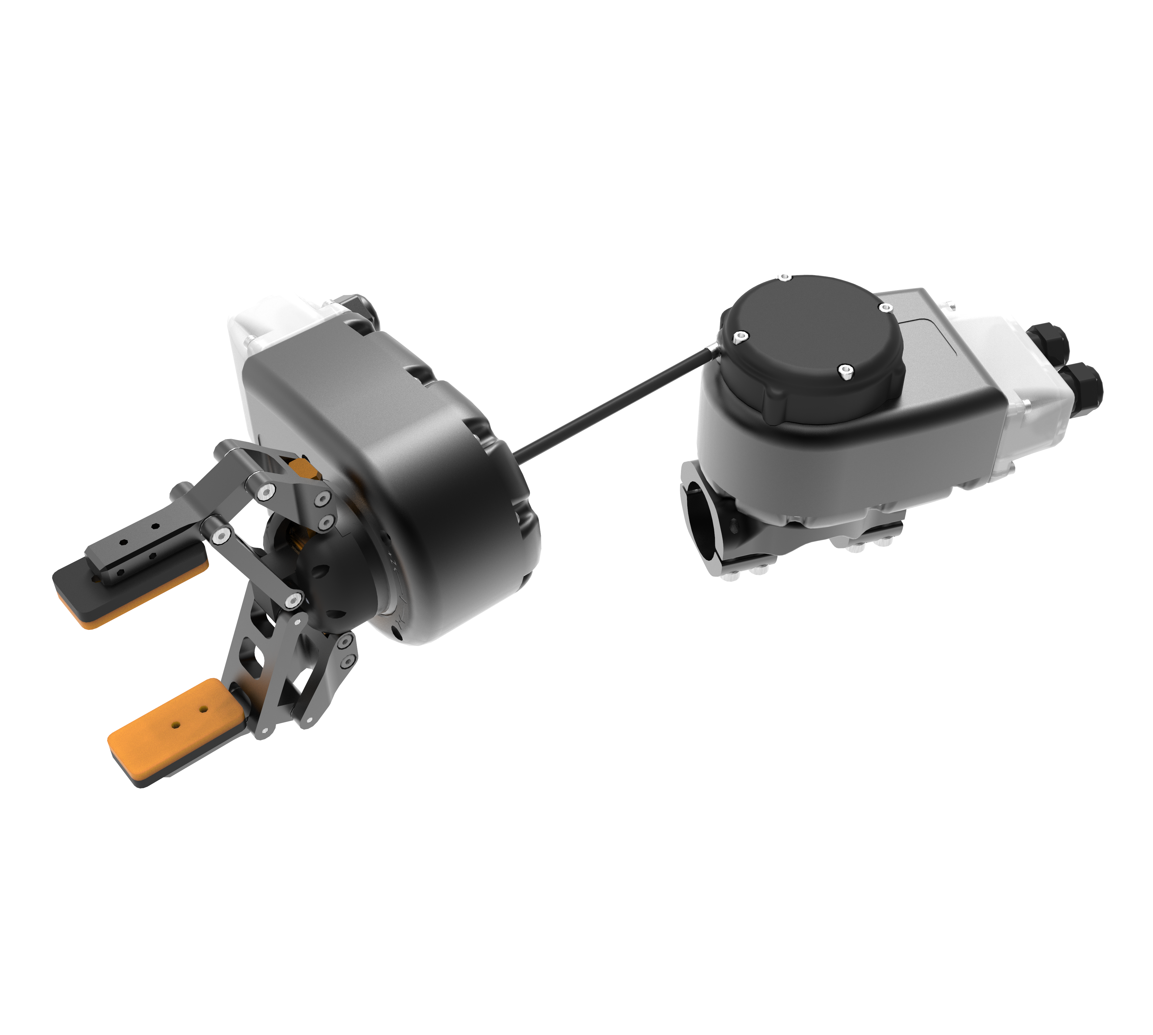
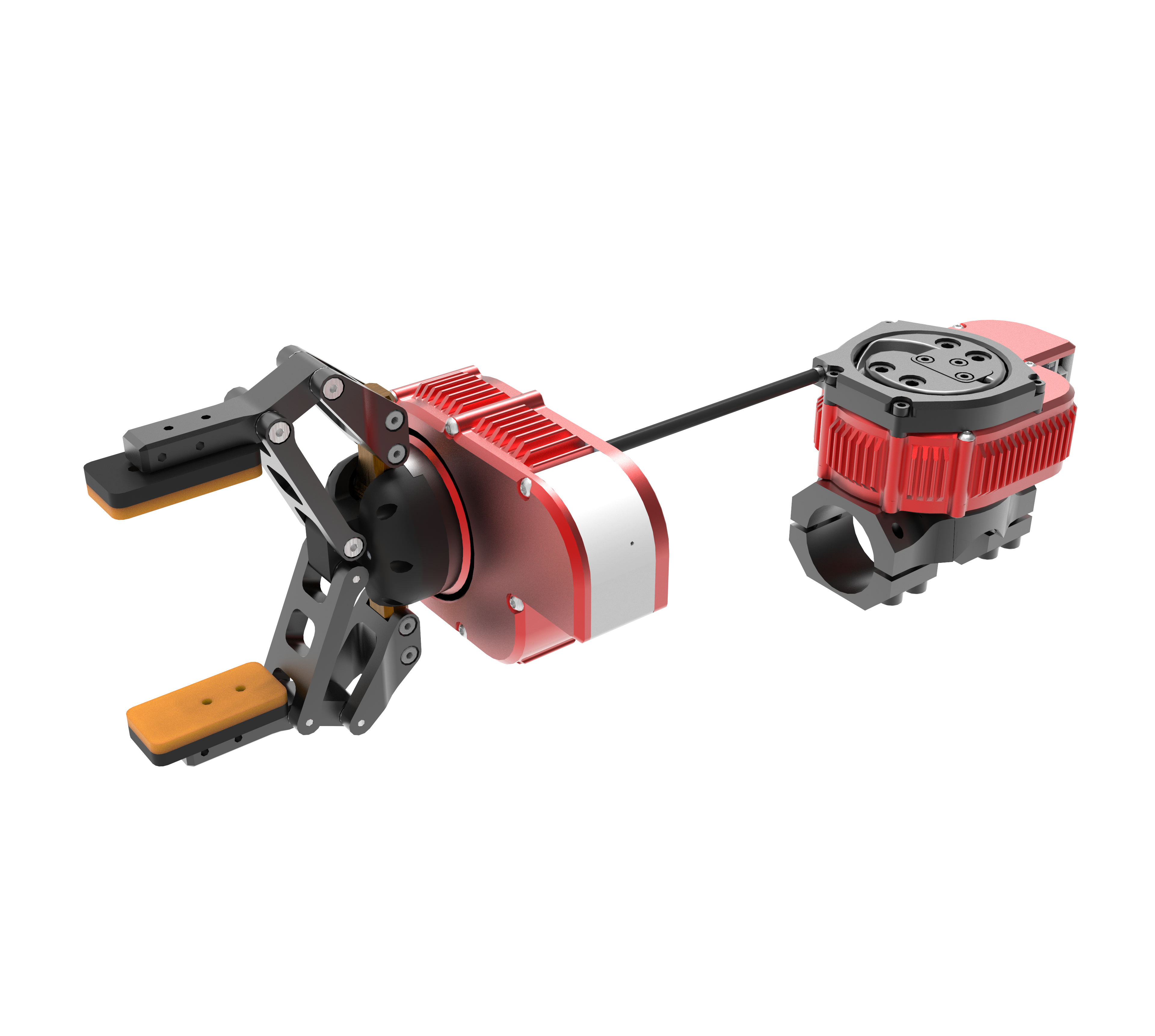
A-2292-01 |
R/T-Series Gripper |
|
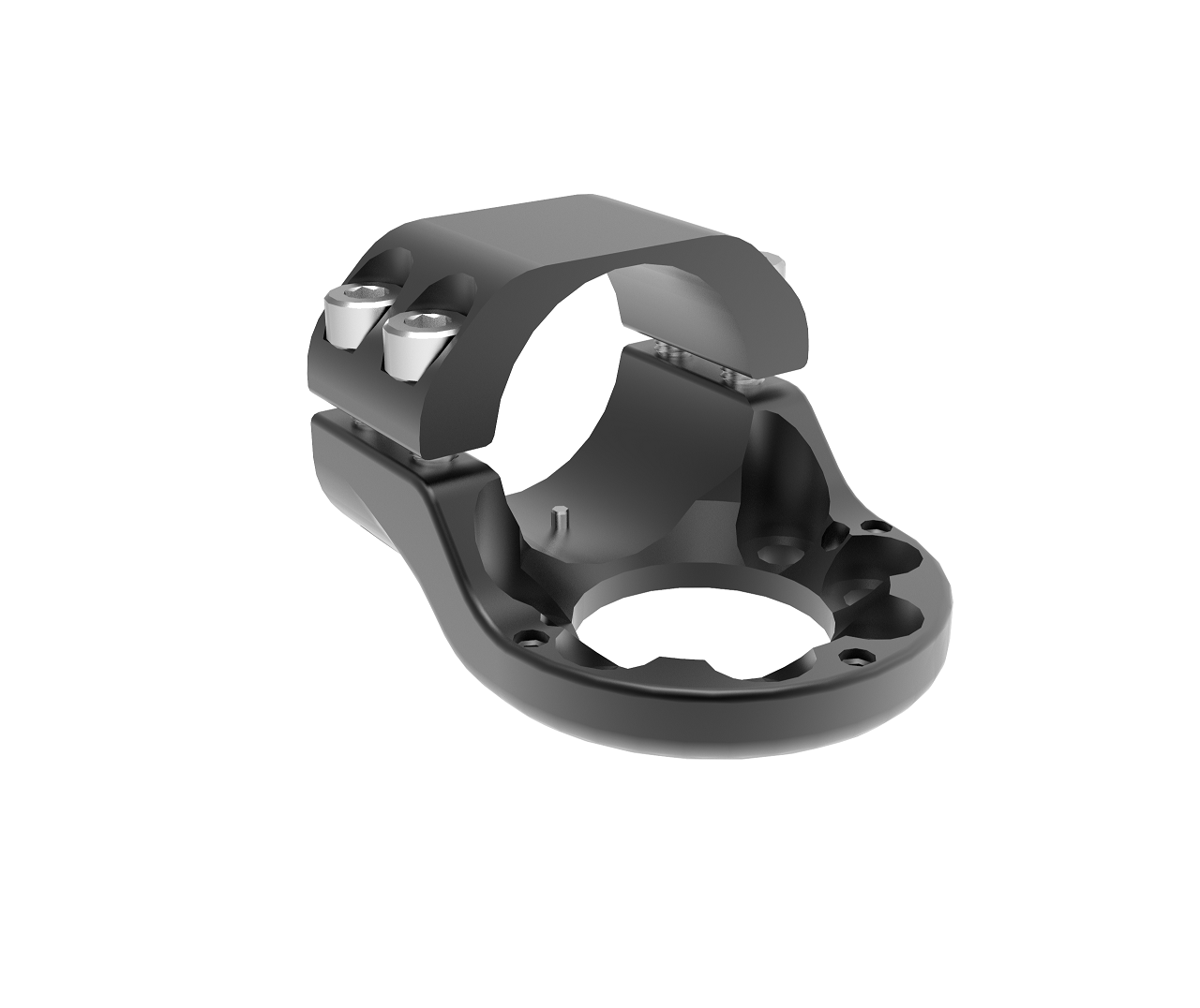
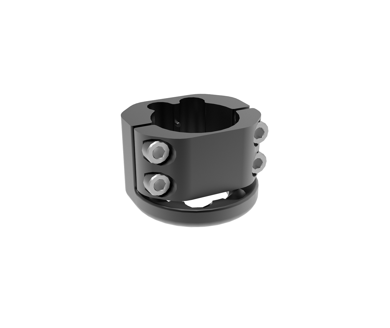
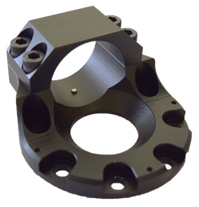
A-2218-01 |
R/T-Series 1.25" Output Tube Adapter w/ indexing pins |
|
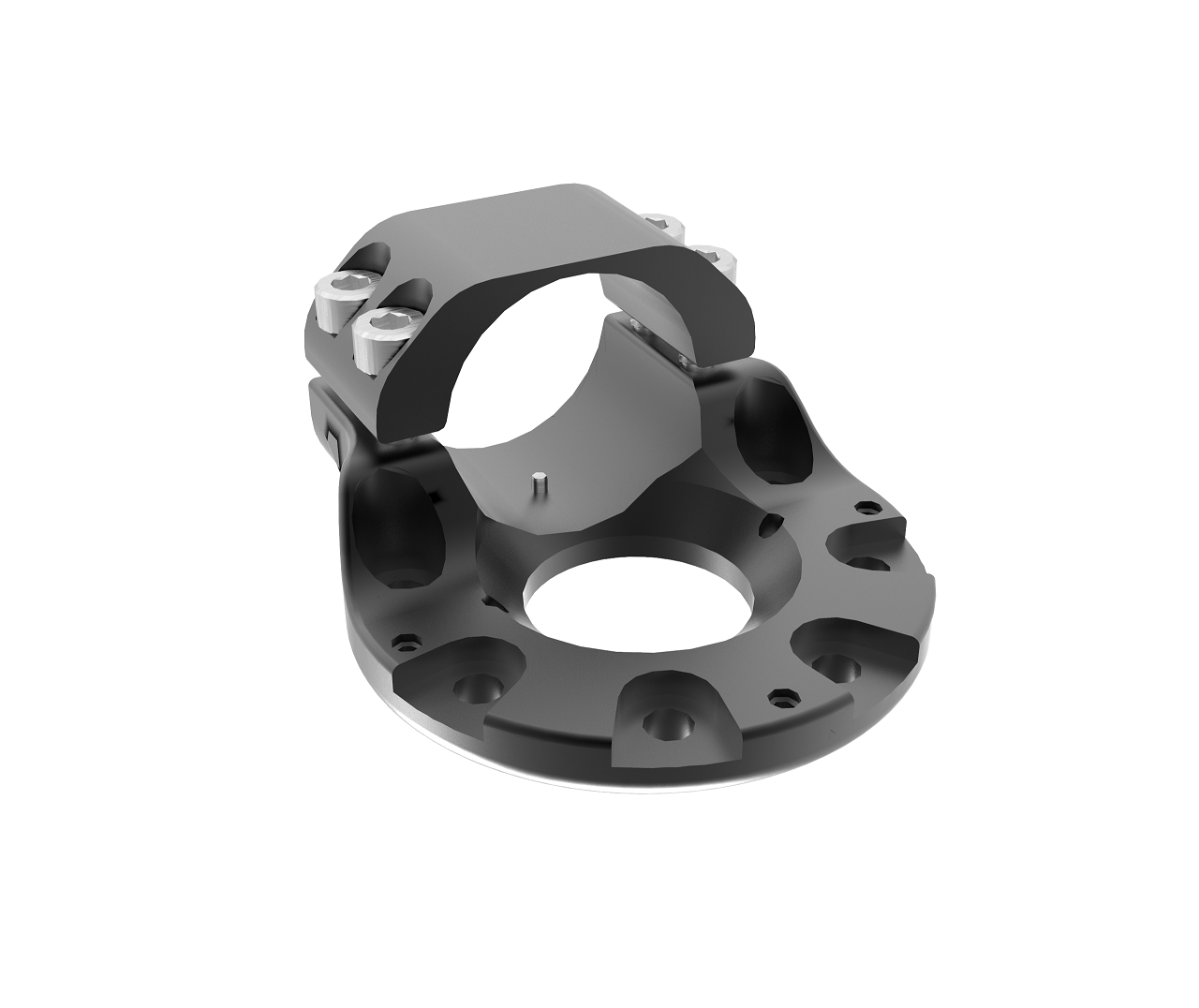
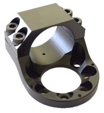
A-2219-01 |
R/T-Series 1.25" Housing Tube Adapter w/ indexing pins |
|
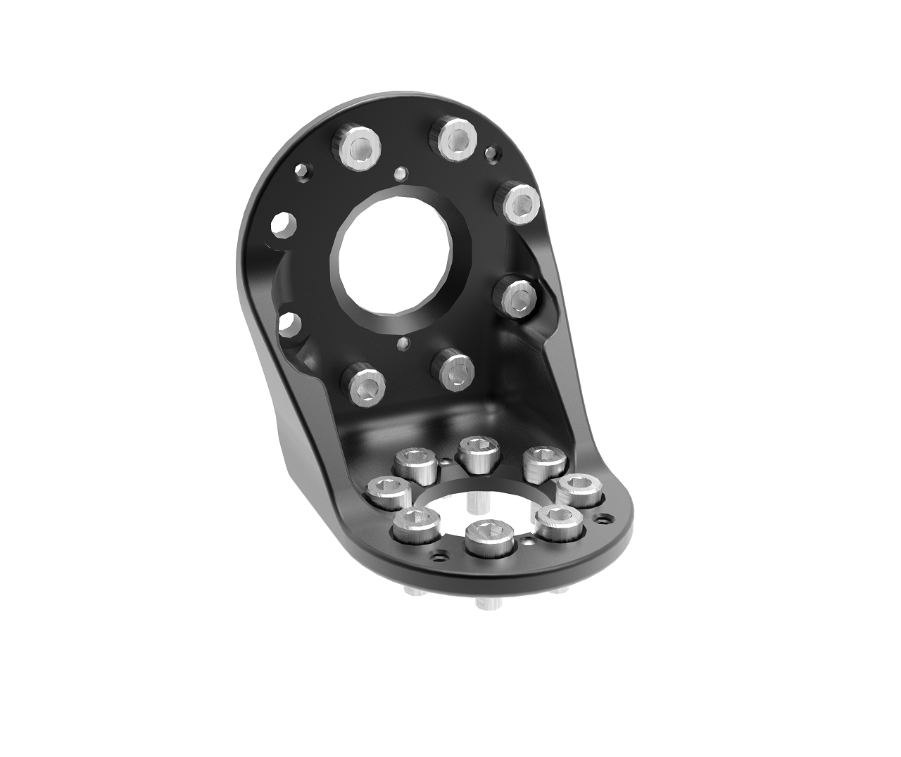
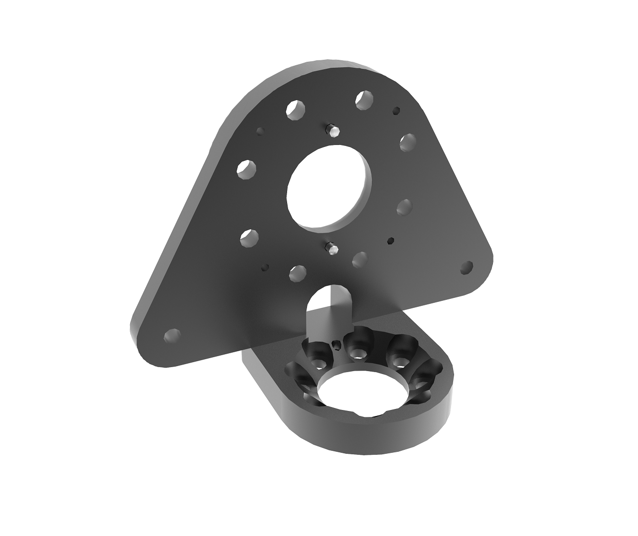
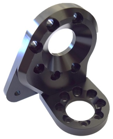
A-2220-01 |
R/T-Series Light 90o Bracket |
|
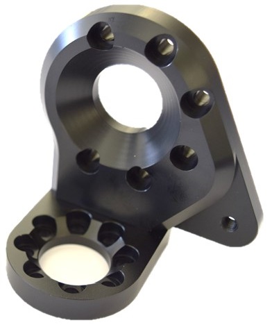
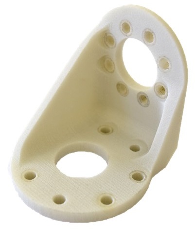
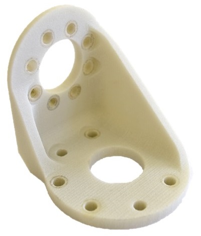
A-2221-01 |
R/T-Series Heavy 90o Bracket |
|
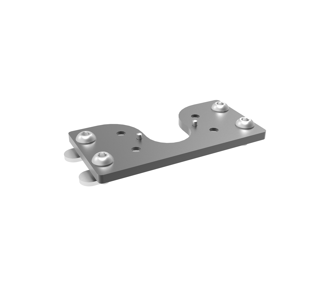
A-2228-01 |
R/T-Series T-Slot Mount Plate 25mm/1" |
|
A-2225-01 |
R/T-Series Output In-line Tube Adapter |
|
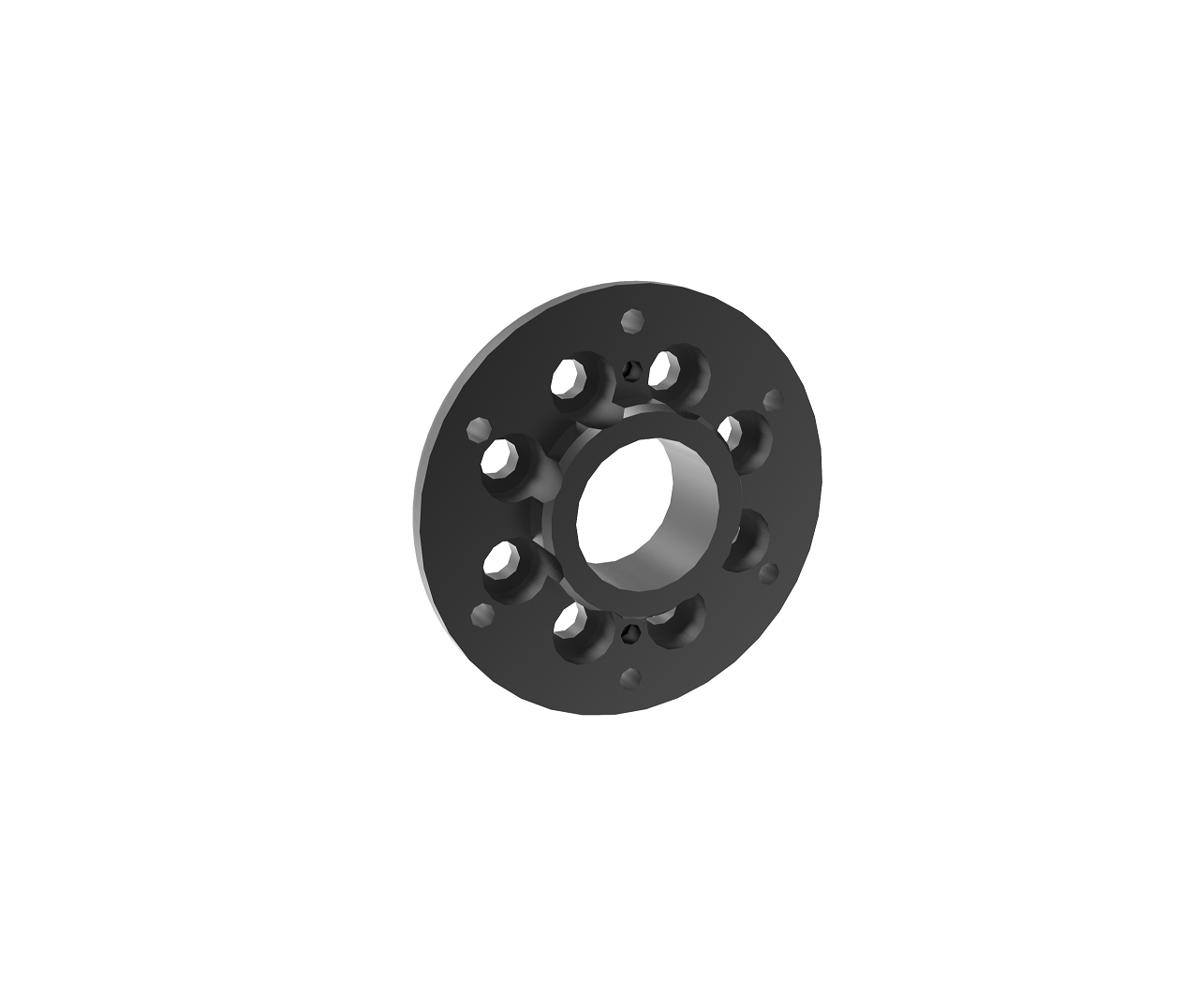
A-2227-01 |
R/T-Series Wheel Adapter |
|
A-2224-01 |
R/T-Series Housing Mid-Tube Adapter |
|
A-2090-01 |
R/T-Series Output Tube Adapter Cover |
|
A-2231-01 |
R/T-Series Housing Tube Adapter Cover |
|
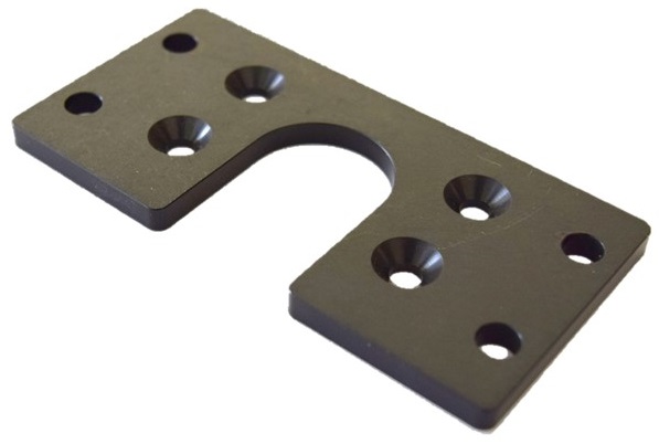
A-2232-01 |
R/T-Series Heavy 90o Bracket Cover |
|
A-2235-01 |
R/T-Series Light 90o Bracket Cover |
|

Electrical Accessories
| Part Number | Description and Drawings | Image |
|---|---|---|
A-2456-02 |
R/T-Series Wiring Kit |
|
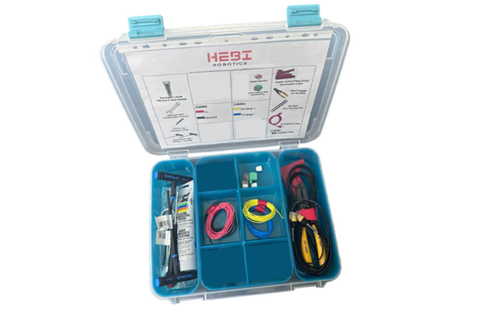
A-2262-02 |
R/T-Series Connection Toolbox |
|
A-2467-01 |
POF Ethernet Converter Connection Kit |
|
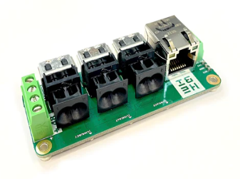
A-2467-02 |
POF Ethernet 4-Port Switch Connection Kit |
|
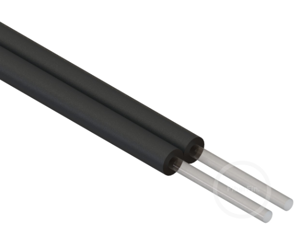
PP-2401-DUP |
1.0mm x 2.2mm POF Duplex Cable |
|
PP-2402-01 |
POF Termination Cutter |
|
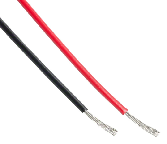
PP-2349-RED |
18AWG Power Wire for R-Series Actuator, Bundle of Black and Red |
|
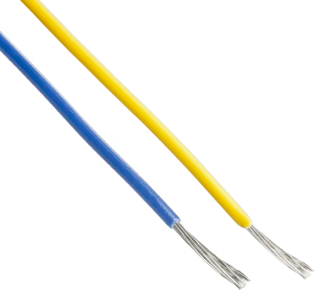
PP-2358-YLW |
22AWG M-Stop Cable for R-Series Actuator, Bundle of Blue and Yellow |
|
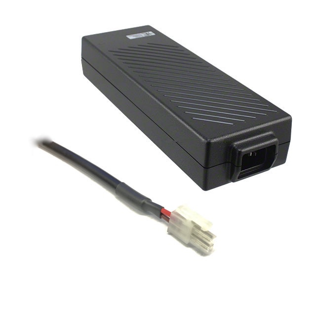
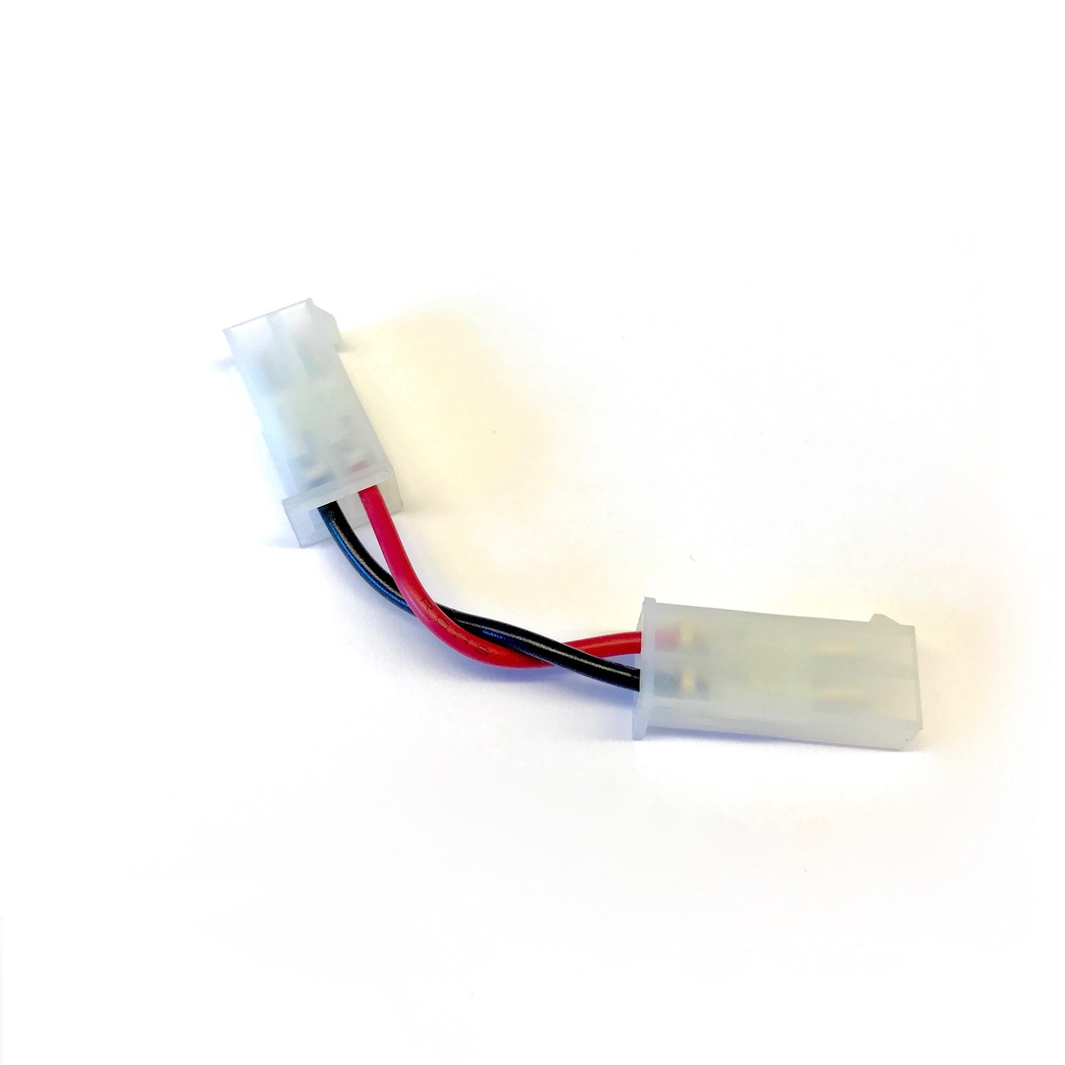
A-2098-36 |
Power Supply w/ Mini-Fit Jr. Terminations |
|

X-Series Accessories
| The X-Series Actuators are Discontinued. Some stock of X-Series Accessories may still remain. If interested, please contact sales@hebirobotics.com. |
|
Legacy X-Series Accessories can physically attach to T-Series and R-Series Actuators, but the housing bolt patterns are offset 2mm in the x-axis which causes some inconsistencies in kinematics and control if not compensated for in the HRDF configuration. Any accessories noted as an R/T-Series Accessory have a symmetric bolt pattern relative to the actuator thru bore. Please refer to the actuator and accessory drawings and CAD files for more information. |
Mechanical Accessories
| Additional drawings and CAD models can be accessed at cad.hebi.us. |
| Part Number | Description and Drawings | Image |
|---|---|---|
A-2138-01 |
X-Series Gripper |
|
A-2038-02 |
X5/X8-Series 1.25" Tube Adapter w/ indexing pins (Output) |
|
A-2039-02 |
X5/X8-Series 1.25" Tube Adapter w/ indexing pins (Housing) |
|
A-2040-01R |
X5/X8-Series 90o Bracket Heavy Duty (Right) |
|
A-2040-01L |
X5/X8-Series 90o Bracket Heavy Duty (Left) |
|
A-2042-01R |
X5/X8-Series 90o Bracket Lite (Right) |
|
A-2042-01L |
X5/X8-Series 90o Bracket Lite (Left) |
|
A-2043-01 |
X5/X8-Series T-Slot Mount Plate 25mm/1" |
|
A-2074-01 |
X5/X8-Series In-line Tube Adapter (Output) |
|
A-2076-01 |
X5/X8-Series Wheel Adapter |
|
A-2089-01 |
X5/X8-Series Mid-Tube Adapter (Housing) |
|
A-2090-01 |
X5/X8-Series Tube Adapter Cover (Output) |
|
A-2091-01 |
X5/X8-Series Tube Adapter Cover (Housing) |
|
Electrical Accessories
| Part Number | Description and Drawings | Image |
|---|---|---|
PP-2059-01 |
High-Flex Ethernet Patch Cable |
|
PE-2026-01 |
X5/8 Power Distribution Board |
|
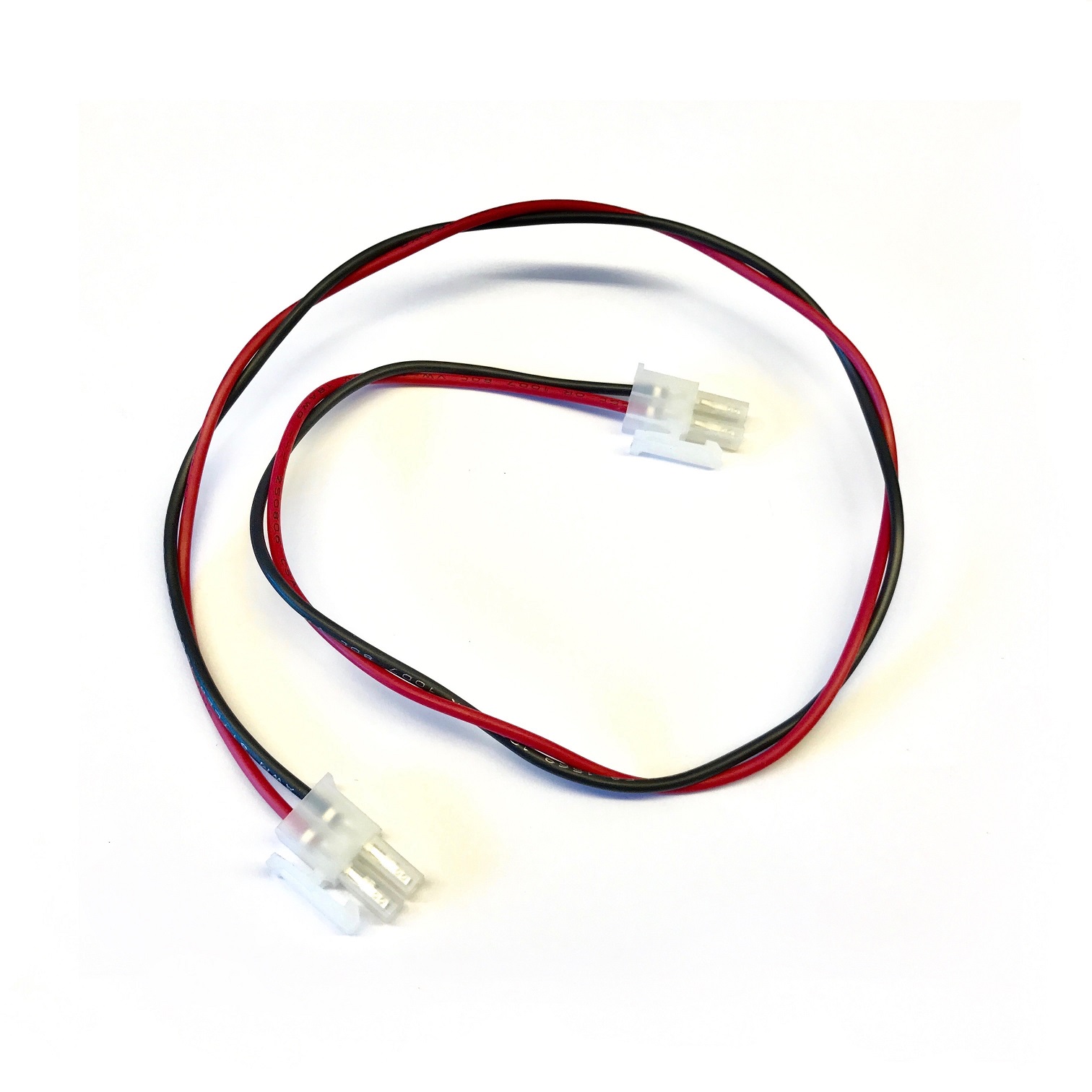
A-2046-12 |
Female/Female Power Cable |
|
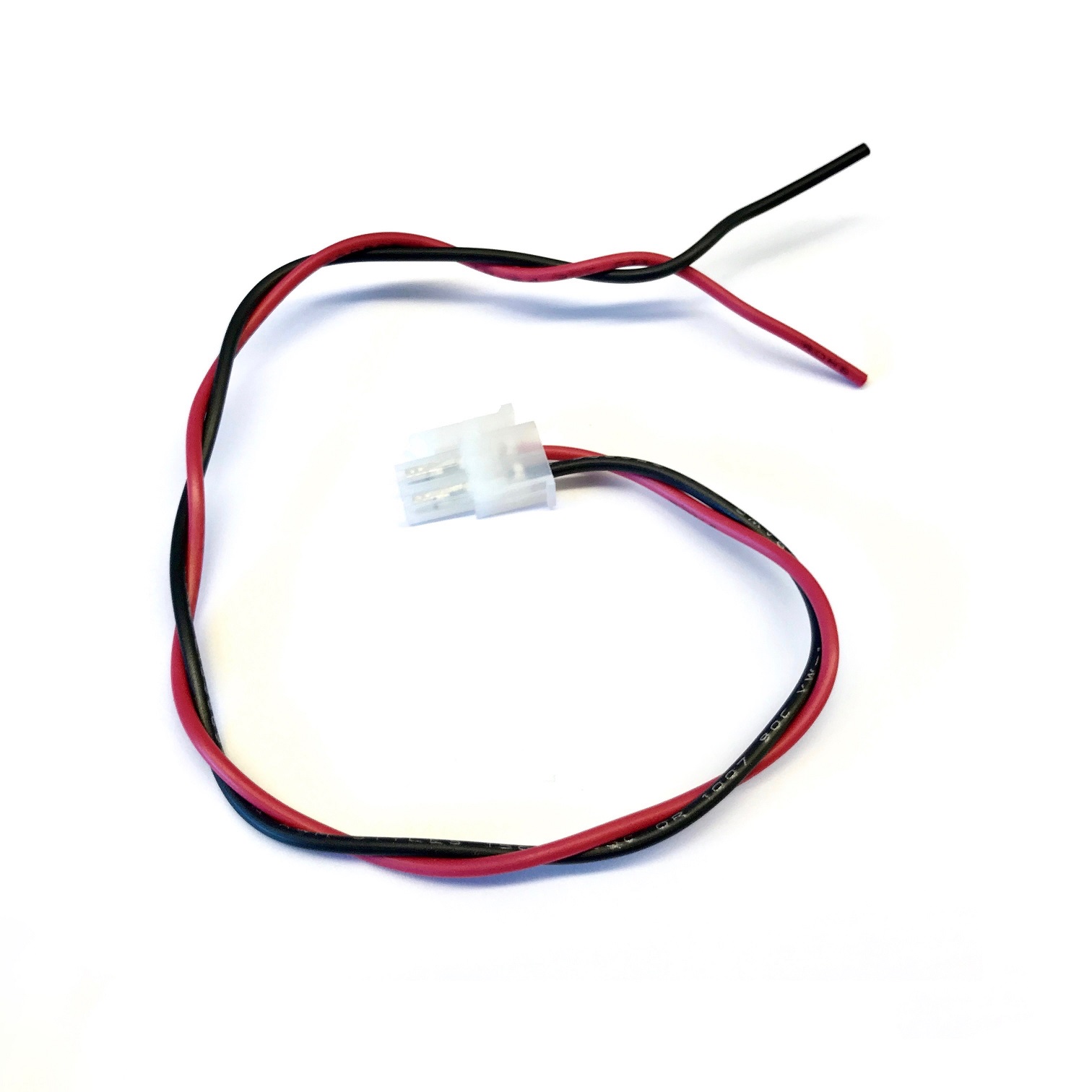
A-2047-12 |
Female/Flying-Lead Power Cable |
|
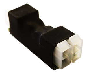
A-2048-02 |
Male/Male Power Cable |
|
A-2098-24 |
Power Supply w/ Mini-Fit Jr. Terminations |
|
Whenever feasible we try to make all HEBI components compatible with existing standards. While we do offer and sell all of the required parts, below are suggestions for some of the most common items that customers may want get from other sources.
Commercial Off-The-Shelf (COTS)
| Type | Comments | Links |
|---|---|---|
Power Supply |
24-48 VDC output |
|
Network Cables |
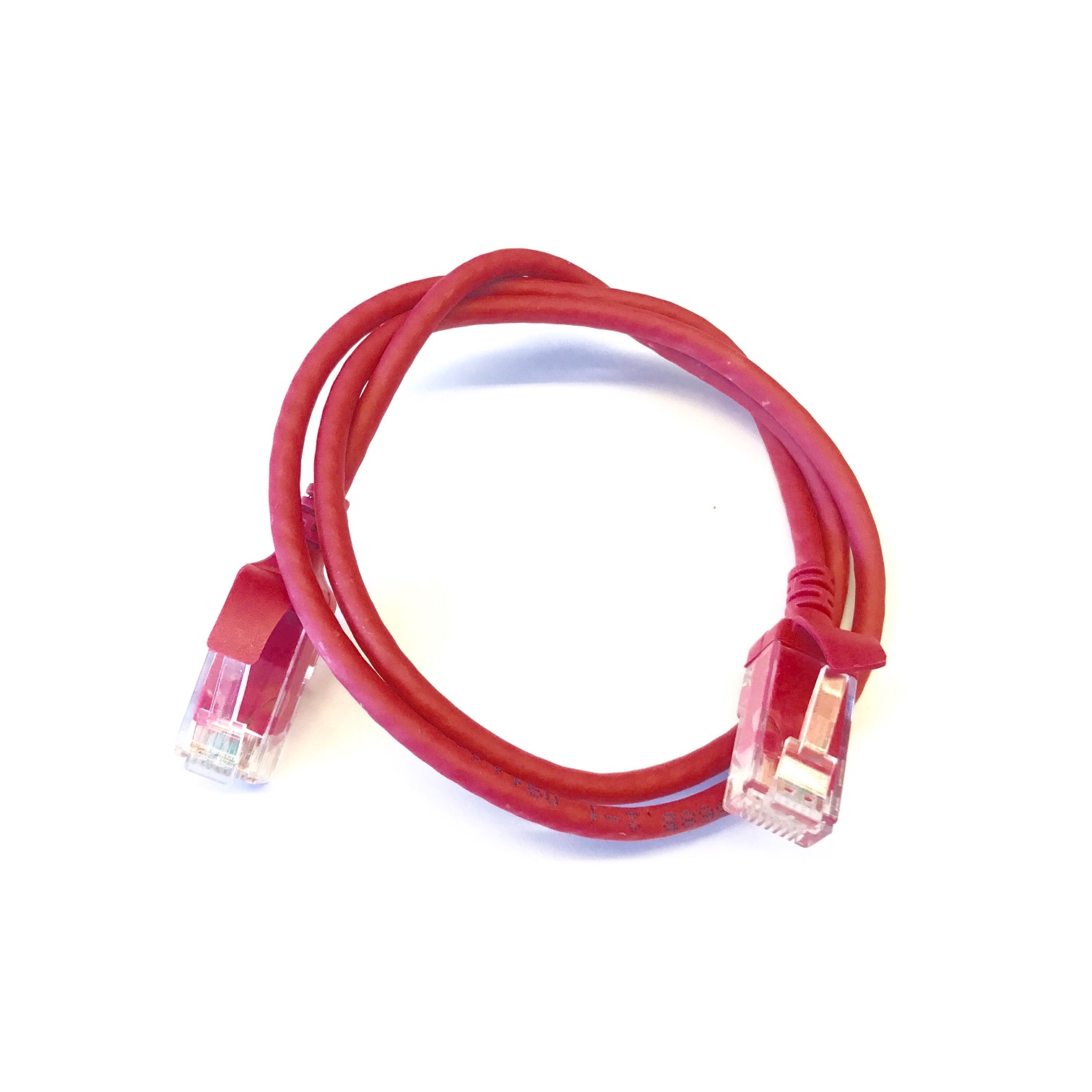
Slim snag-less Ethernet cables |
|
Power Supply |
7V-24 VDC output |
Tubes and Tube Accessories
These Tubes and Tube Accessories are compatible with both X-Series and R-Series Actuators and their corresponding Accessories.
| Part Number | Description and Drawings | Image |
|---|---|---|
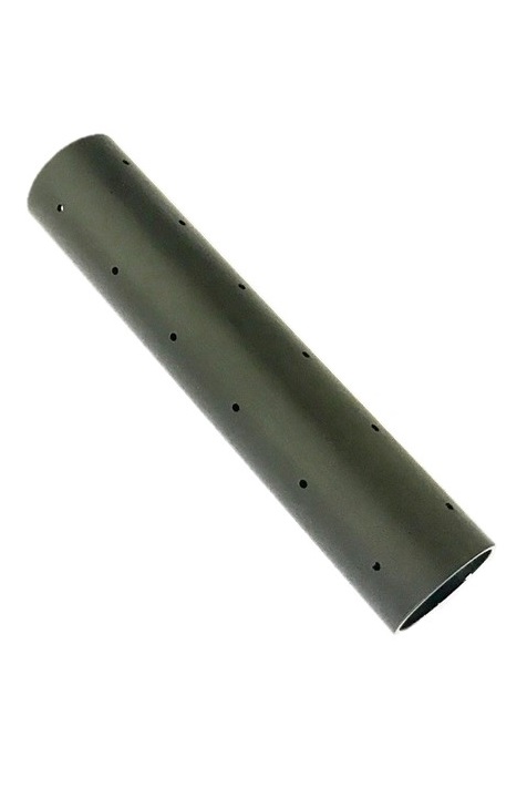
PM-2200-01 |
1.25" OD Aluminum Tube w/ indexing holes, 150mm length |
|
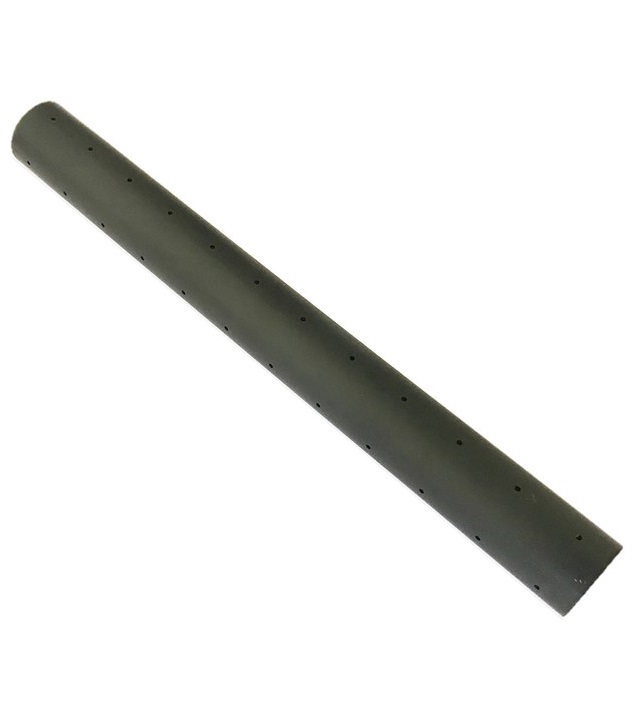
PM-2200-02 |
1.25" OD Aluminum Tube w/ indexing holes, 300mm length |
|
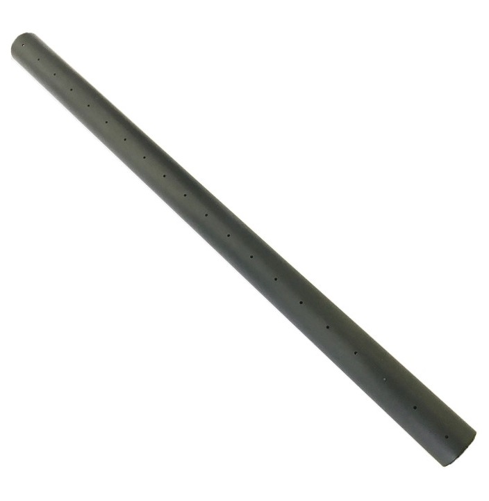
PM-2200-03 |
1.25" OD Aluminum Tube w/ indexing holes, 500mm length |
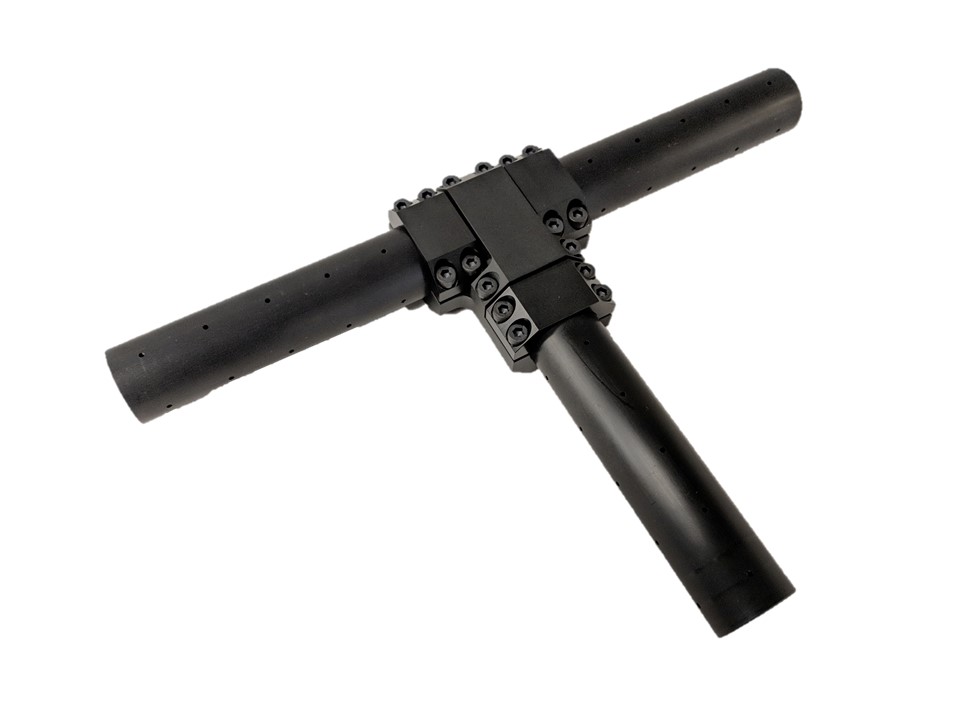
|
A-2118-01 |
Tube-to-Tube T-Adapter for 1.25" OD Tube |
|
A-2129-01 |
Tube-to-Tube Plus-Adapter for 1.25" OD Tube |
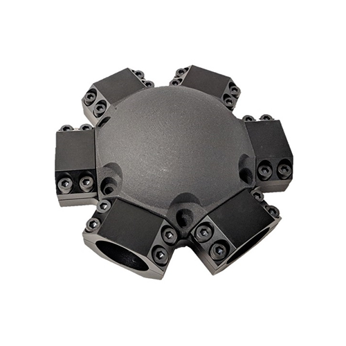
|
A-2095-01 |
Six Tube Adapter for 1.25" OD Tube |
|

Battery
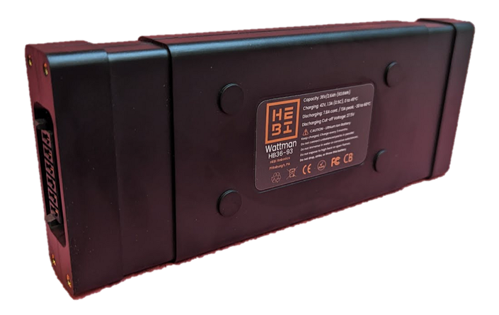
The HEBI “Wattman” Battery is our modular, airline-ready Lithium Ion battery pack designed for robotics applications. This 36V 93.6Wh pack is under the 100Wh limit for lithium ion batteries in carry on luggage and comes UN-38.3 and CB-IEC62133 certified.
Each battery pack is equipped with a blade-type power connector, M3 mounting holes, and embossed features for maximum implementation flexibility. Built-in enable circuitry keeps the connector de-energized for storage.
Integrated LEDs provide a quick charge estimate on demand. An integrated BQ34Z100-G1 "Fuel Gauge" IC provides more accurate state-of-charge information and is accessible through I2C.
Pack Arrangement |
10S1P ITR18650-2600P Lithium Ion Cells |
Capacity |
93.6Wh (36V, 2.6Ah) |
Charge Profile |
1.3A (0.5C), 0 to 45°C |
Discharge Profile |
7.8A Cont. / 13A Peak, -20 to 60°C |
Connector |
Battery: SAMTEC MPS-06-7.70-03-L-V |
Dimensions |
Battery: 206mm x 80mm x 25mm |
Weight |
Battery: 650g |
CAD |
Battery: PDF Drawing |
Datasheet |
Standard Connector Cap
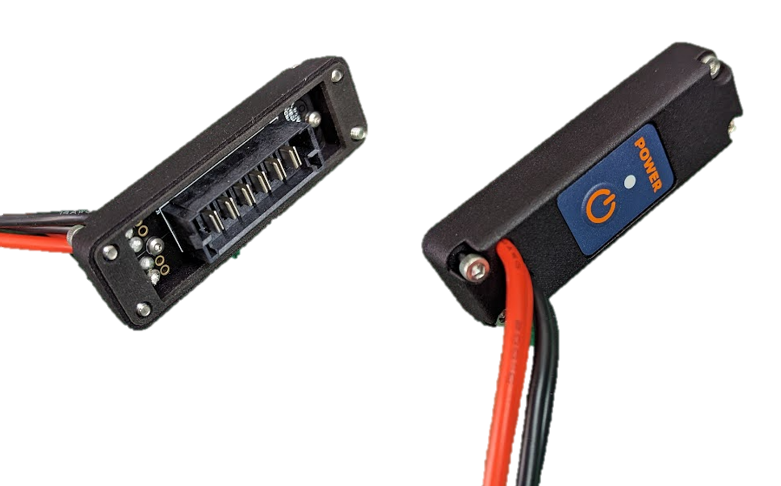
HEBI sells a standard connector cap (A-2473-01) that has the necessary interfaces to use the HEBI Wattman Battery out-of-the-box. The connector cap comes standard with a membrane on/off button and two Anderson Powerpole connector pairs, but can be customized to customer application requirements.
CAD |
Standard Connector Cap: PDF Drawing |
CR1 Camera Module
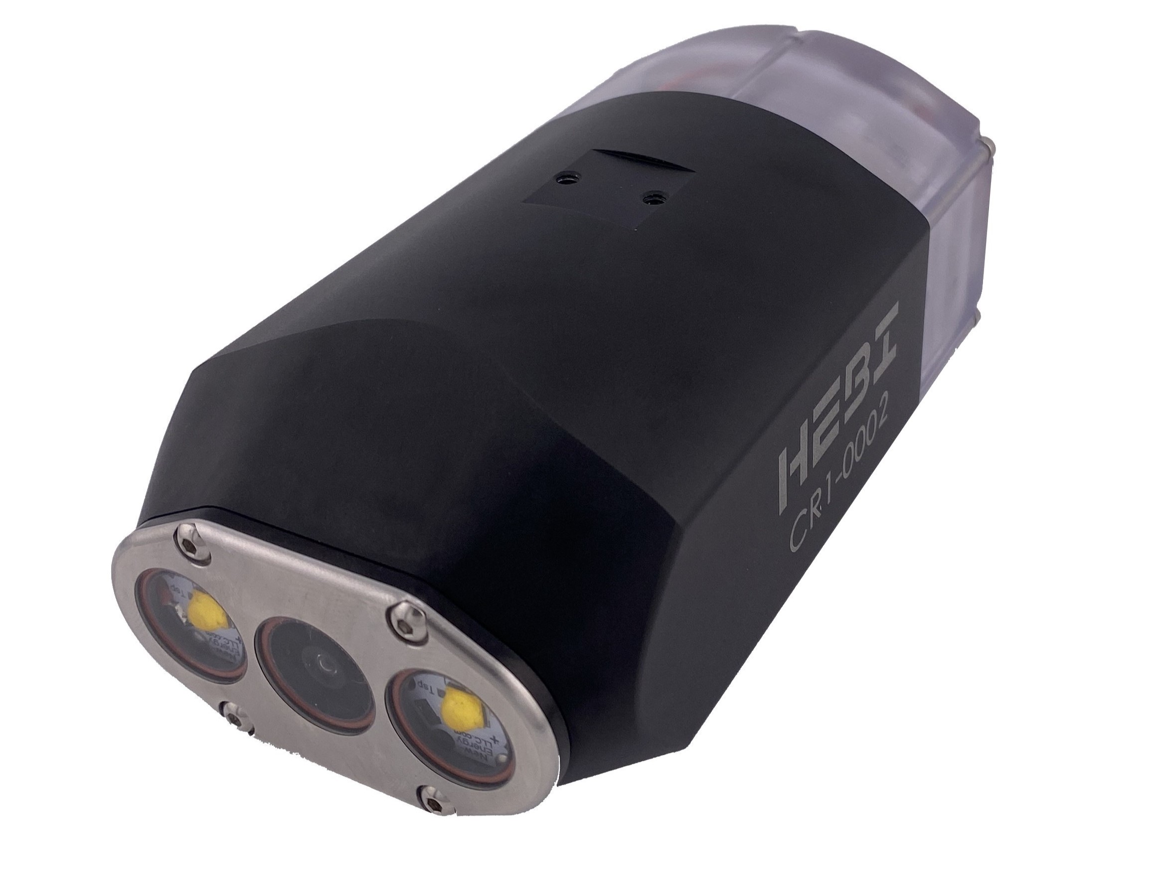
The CR1 Inspection Camera is a sealed, self contained module that can be mounted externally to a kit to provide the user with additional camera coverage.
Connector |
A-2530-02: RJ45 + 18awg wire-seals |
Dimensions |
A-2530-02: 165mm x 77mm x 67mm |
Weight |
750g |
Camera |
1080p HD video output over RTSP stream |
CAD |
A-2530-02 (RJ45): PDF Drawing |
Datasheet |
Quick start guide for the CR1 camera module can be found here.
Kits
In addition to individual components, we have designed ready-to-go robotic systems we refer to as "kits". All kits include actuators, connecting accessories, wiring, assembly instructions, and example code.
| All kits have a suggested set of HEBI actuators. It is possible to adjust parameters such as payload or speed with a different configuration of actuators. |
| Part Number | Description and Info | Image |
|---|---|---|
A-2302-01 |
4 - Degree of Freedom (DoF) |
|
A-2240-04 |
4 - Degree of Freedom (DoF) |
|
A-2240-05 |
5 - Degree of Freedom (DoF) |
|
A-2240-05G |
5 - Degree of Freedom (DoF) |
|
A-2240-06 |
6 - Degree of Freedom (DoF) |
|
A-2240-06G |
6 - Degree of Freedom (DoF) |
|
A-2303-01 |
7 - Degree of Freedom (DoF) |
|
A-2257-01 |
Lily |
|
A-2361-01 |
R-Series Tracked Mobile Base |
|
A-2313-01 |
R-Series Mecanum Mobile Base |
|
A-2363-01 |
Tready |
|
A-2403-02 |
Maggie |
|
A-2403-03TM |
Mack |
|
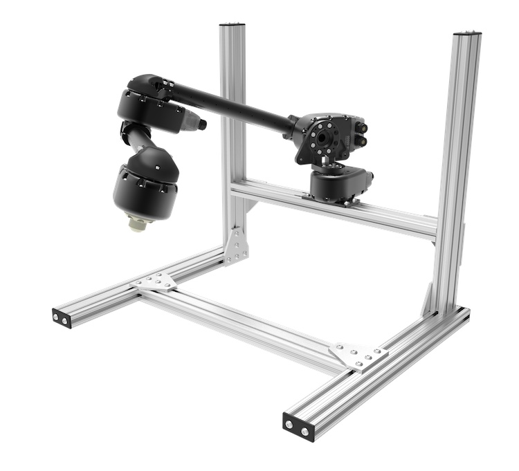
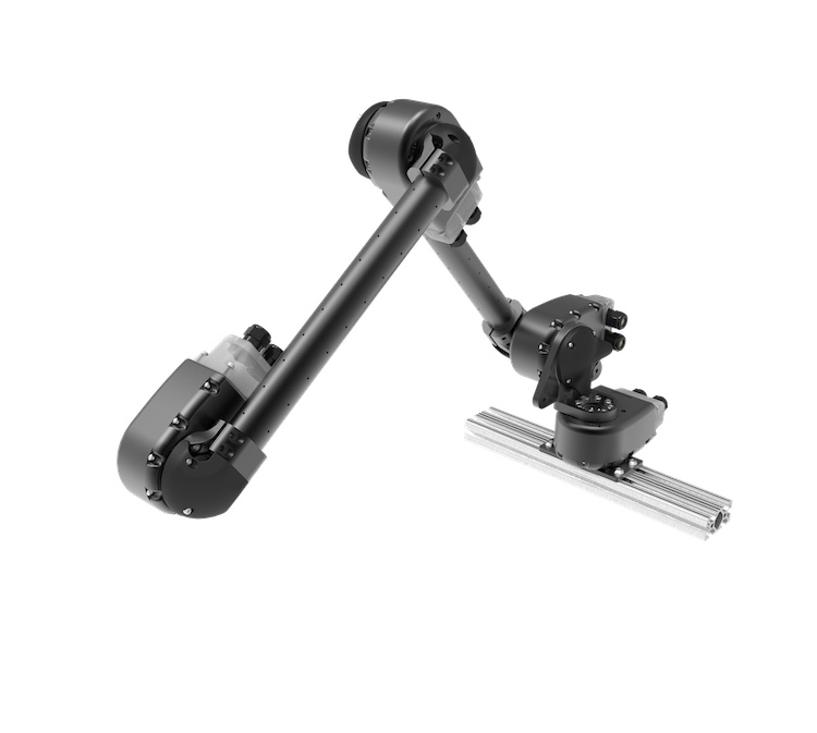
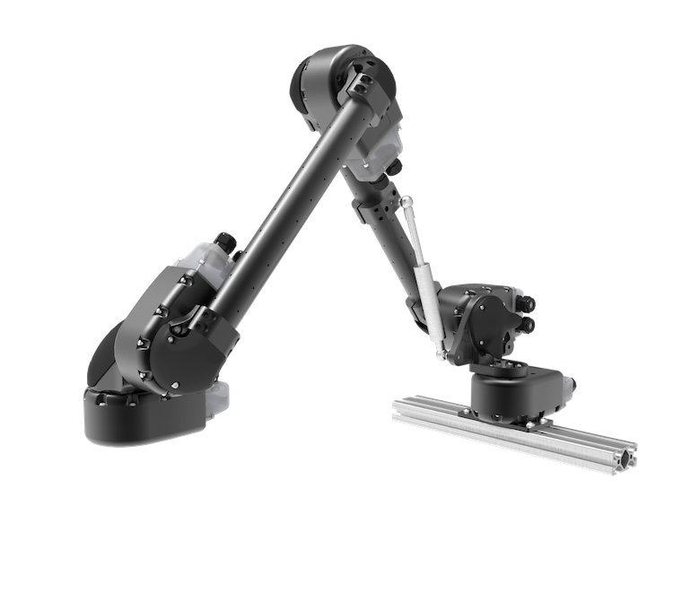
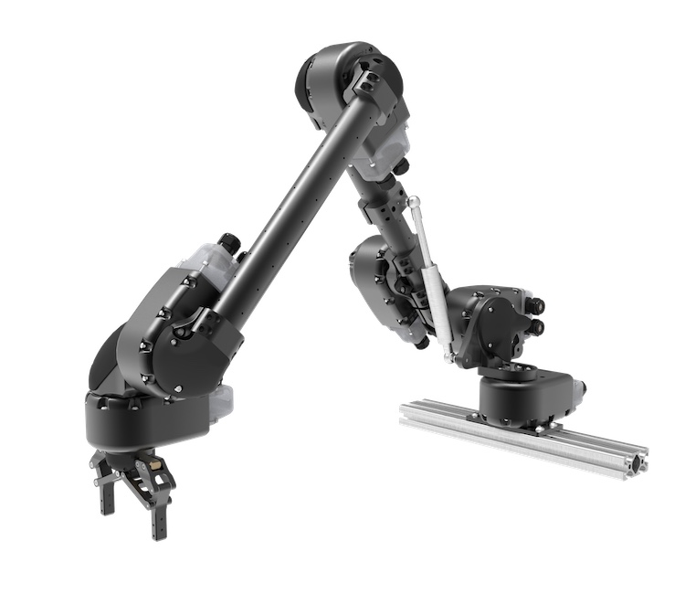
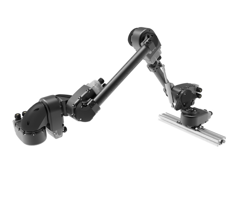
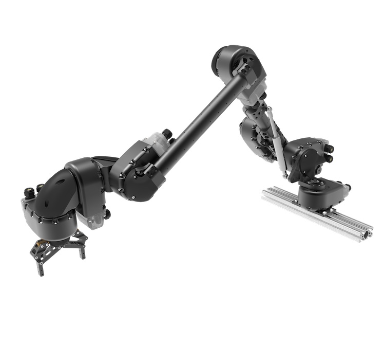
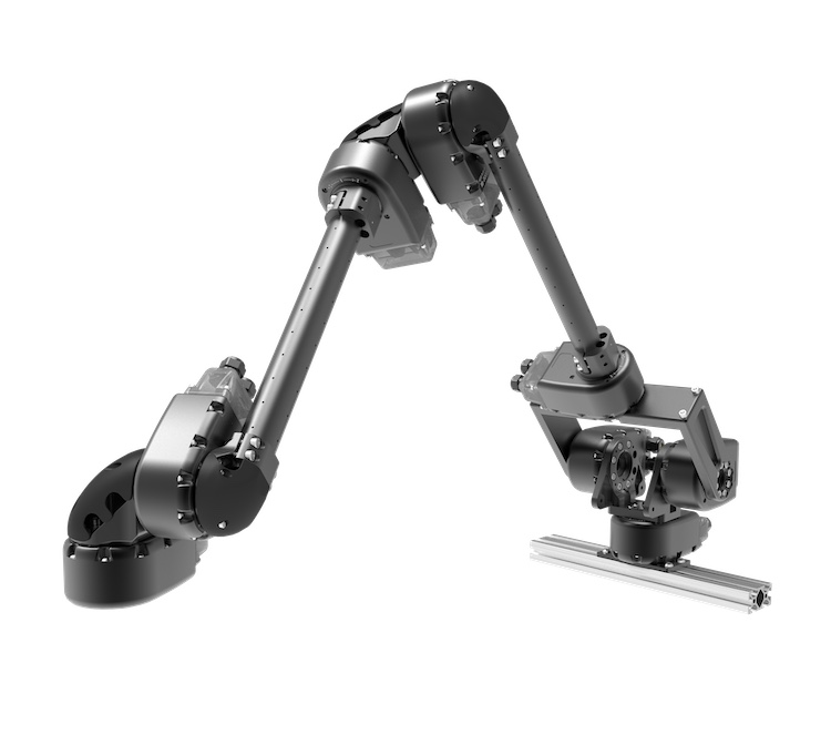
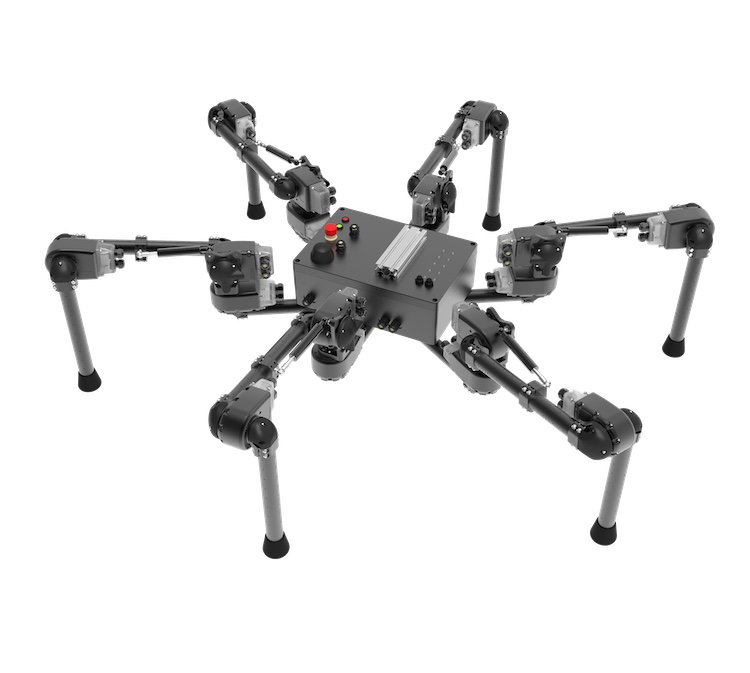
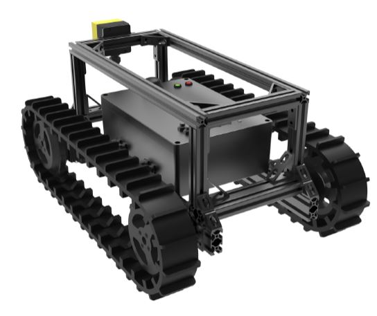
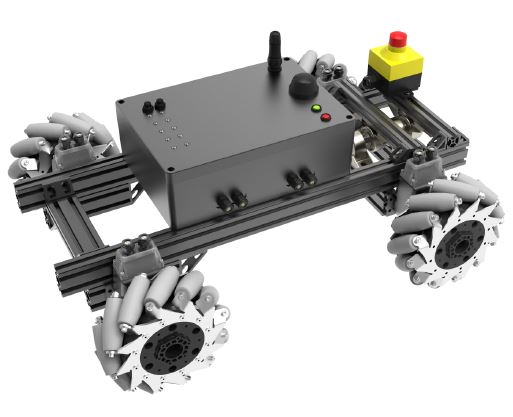
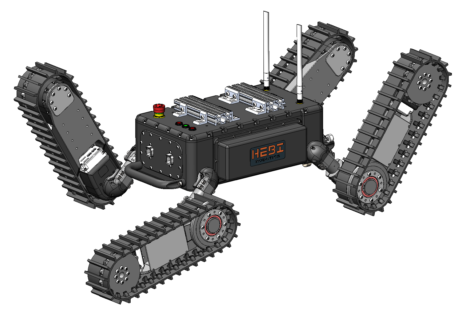
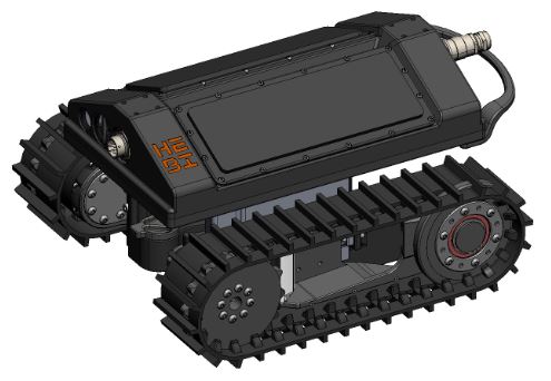
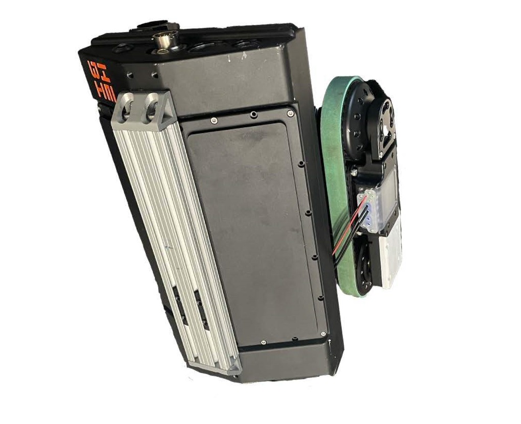
| All T-Series Kits use R/T-Series Accessories. Kits listed below that mention "Similar to X-Series Kits" refer to the configuration of Actuators. All accessories will need to be updated to the latest part numbers. Technical specifications and payloads between new T-Series kits and legacy X-Series kits will be relatively the same. |
| Part Number | Description and Info | Image |
|---|---|---|
A-2590-01 |
4 - Degree of Freedom (DoF) |
|
A-2580-04 |
4 - Degree of Freedom (DoF) |
|
A-2580-05 |
5 - Degree of Freedom (DoF) |
|
A-2580-06 |
6 - Degree of Freedom (DoF) |
|
A-2582-07 |
7 - Degree of Freedom (DoF) |
|
A-2591-01 |
T-Series Rosie |
|
A-2592-01 |
Omni-Directional Drive Mobile Base |
|
A-2598-01 |
Differential Drive Mobile Base |
|
A-2599-01 |
Mecanum Drive Mobile Base |
|
A-2593-01 |
T-Series Daisy |
|
A-2595-01 |
T-Series Igor |
|
A-2132-02 |
Modular Chassis Kit (Square) |
|
A-2127-02 |
Modular Chassis Kit (Hexagonal) |
|
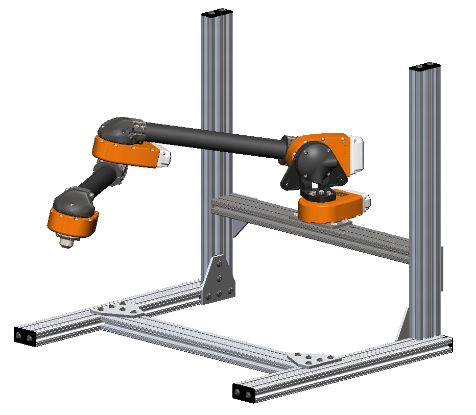
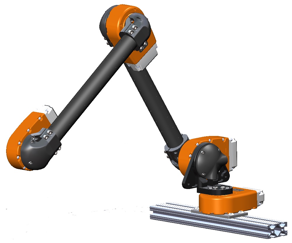
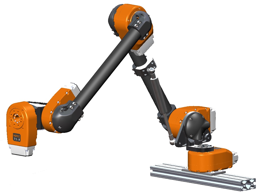
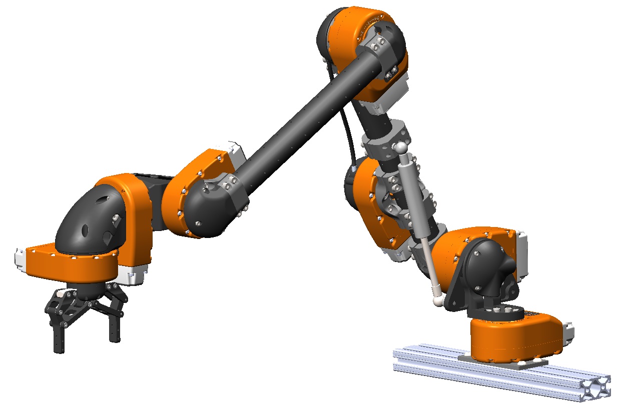
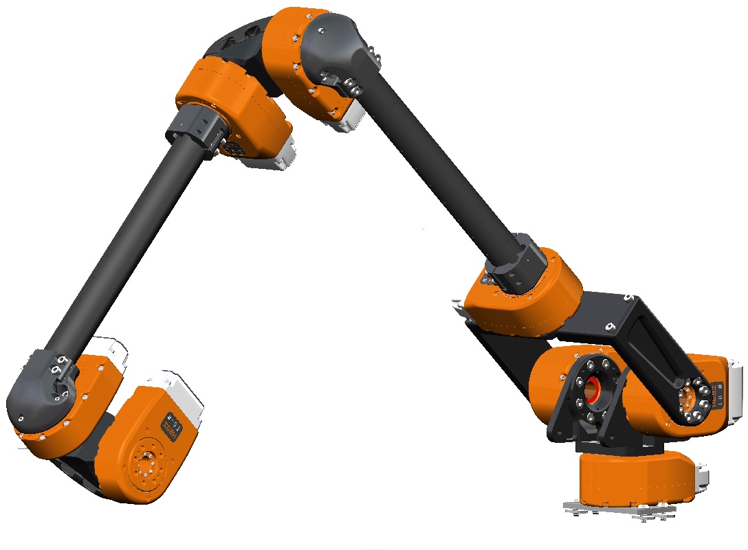
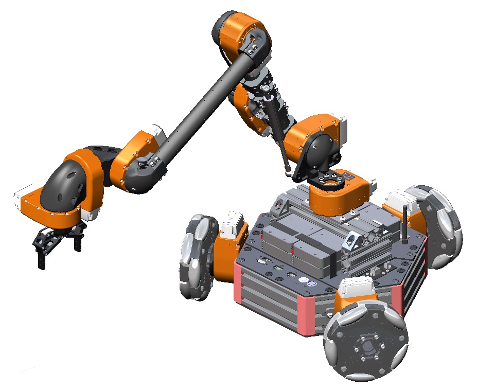
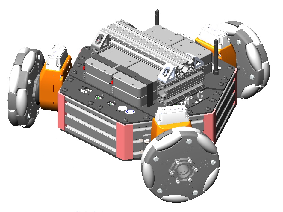
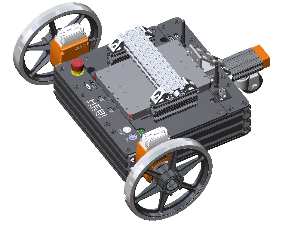
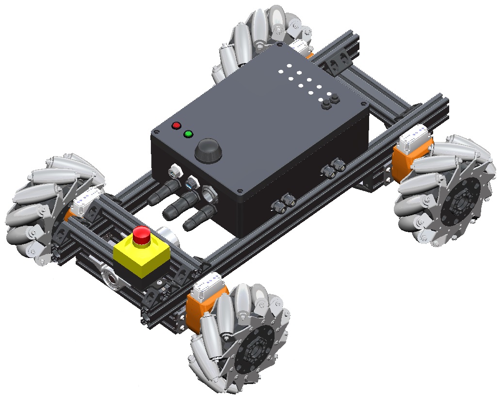
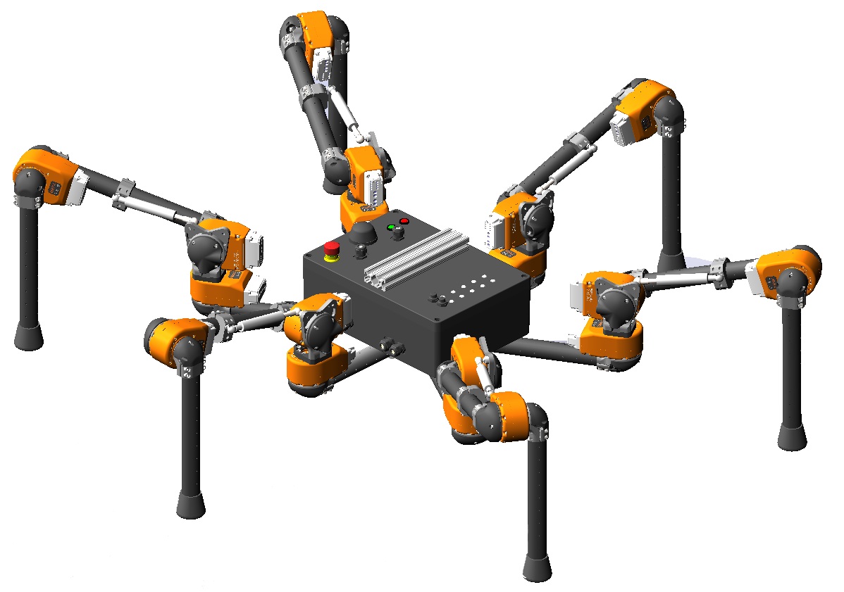
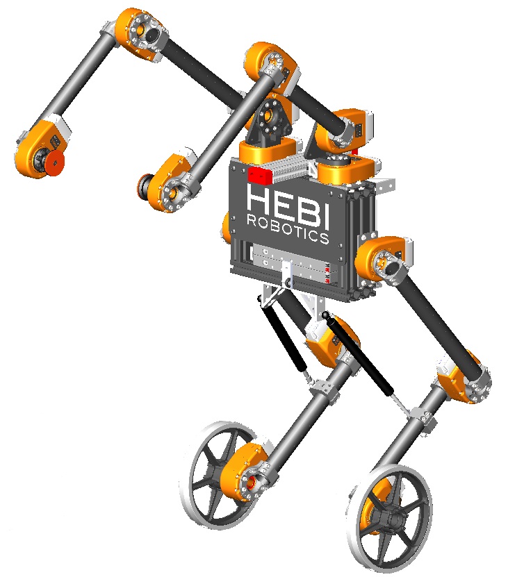
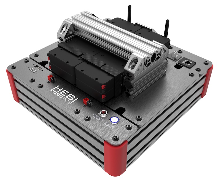
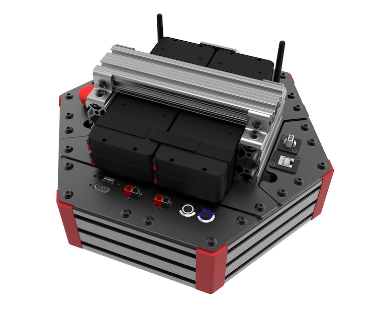
| Part Number | Datasheets and Manuals |
|---|---|
A-2084-01 |
X-Series 4-DoF SCARA Arm |
A-2085-04 |
X-Series 4-DoF Arm |
A-2085-05 |
X-Series 5-DoF Arm |
A-2085-06 |
X-Series 6-DoF Arm |
A-2099-07 |
X-Series 7-DoF Double Shoulder Arm |
A-2160-01 |
X-Series Rosie |
A-2049-01 |
X-Series Daisy |
A-2058-02 |
X-Series Igor |
A-2120-01 |
X-Series Edward |
Assembly Instructions
Tubing and Tube Adapters
HEBI tubes and tube adapters are an easy way to create systems such as robotic arms. The indexing holes allow for precise length and twist measurements for your robot’s kinematics (see R8 Link in Kinematics section). Our tubes come in standard lengths of 150mm, 300mm, and 500mm, but are easily cut down to custom lengths. Tubes were chosen for their lightweight and thru bore allowing for easy installation of wires (see Module Documentation).
|
|
|
|
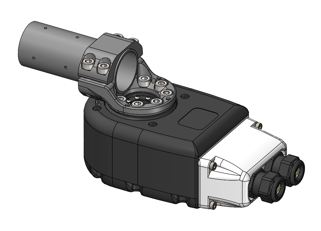
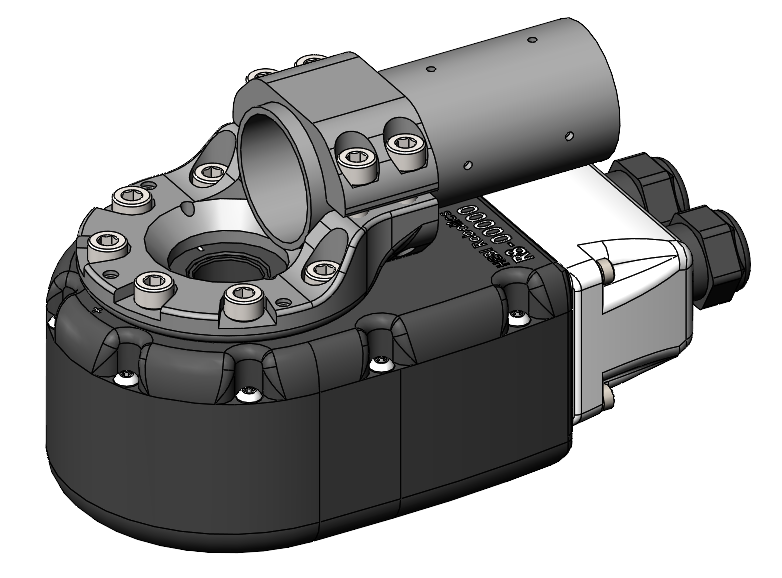


Right Angle Brackets
HEBI right angle brackets allow you to use T-Series and R-Series Actuators in perpendicular axes, commonly needed for bases or end effectors of robotic arms. These brackets can be setup in both a 'Left' and 'Right' configuration making it easy to setup your system specific to your application’s needs.
Lightweight Bracket
This bracket is black anodized aluminum and have been setup for only an 'outside' configuration. It are best for connecting end effectors to a final "wrist" degree of freedom on robotic arms.
|
|
|
|
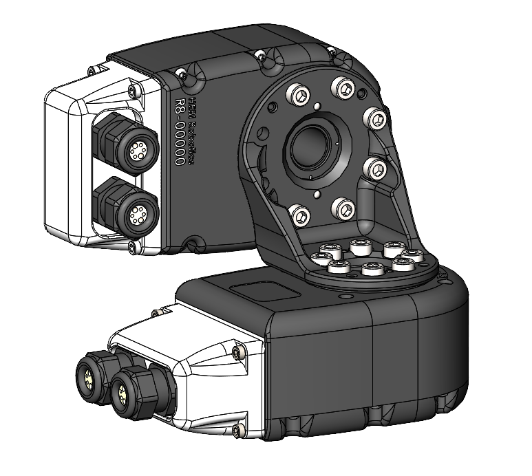
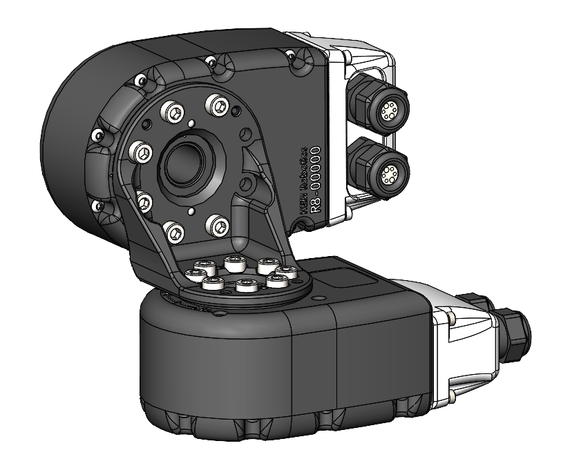
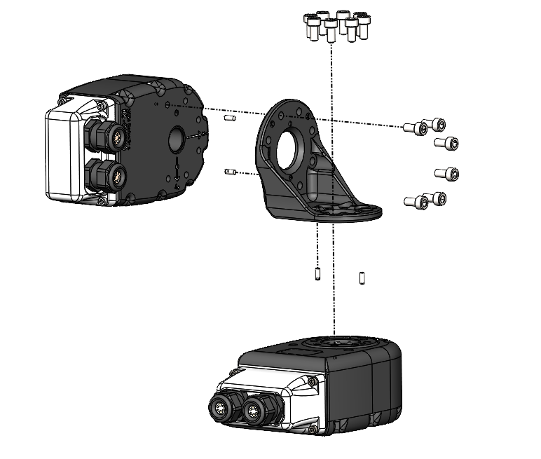
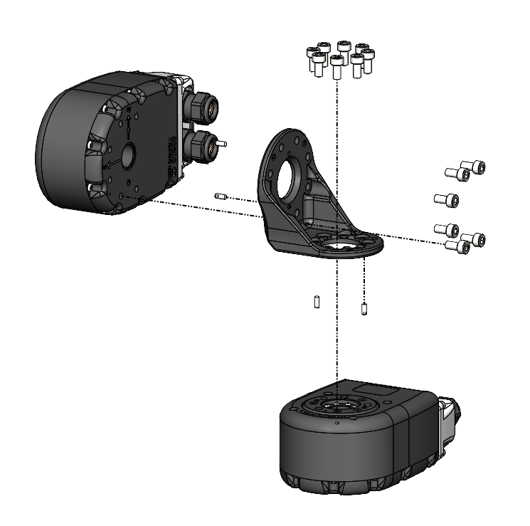
Heavy Duty Bracket
This bracket is black anodized aluminum and are best for bases of robotic arms. It is symmetric so you can mount the vertical actuator in the 'Left' or 'Right' Configuration as well as in an 'inside' or 'outside' configuration as shown below.
|
|
|
|
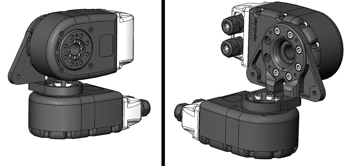
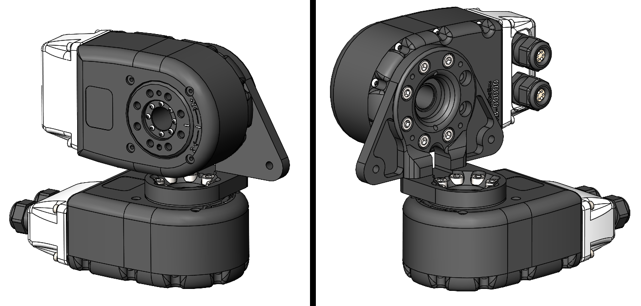
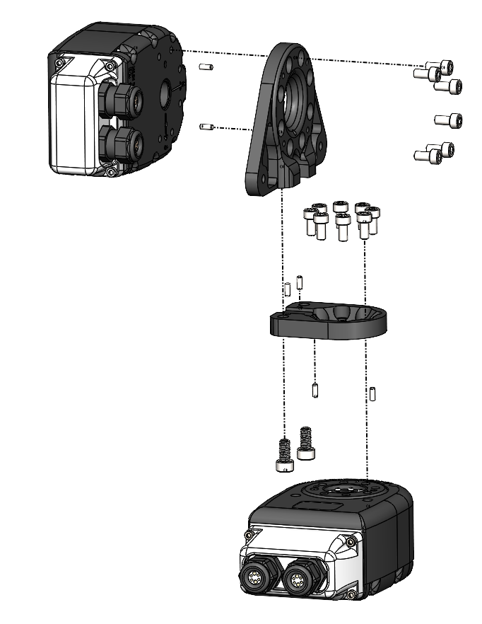
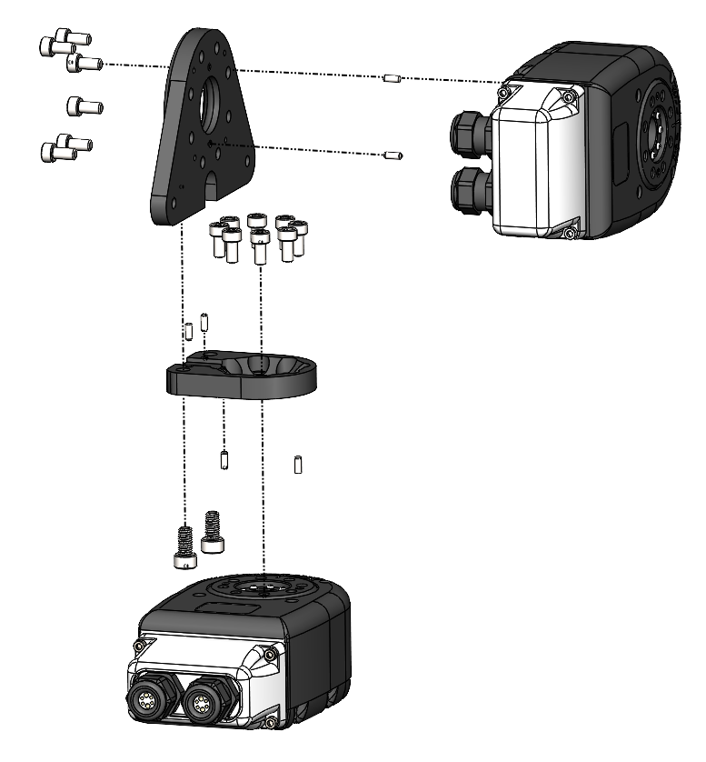
T-Slot Adapter
Need an easy solution for mounting your robotic system? Enjoy building structures out of t-slot aluminum extrusion? The t-slot adapter is for you! This plate helps you attach any T-Series or R-Series Actuator to standard 25mm or 1 inch t-slot aluminum extrusion.
|
|
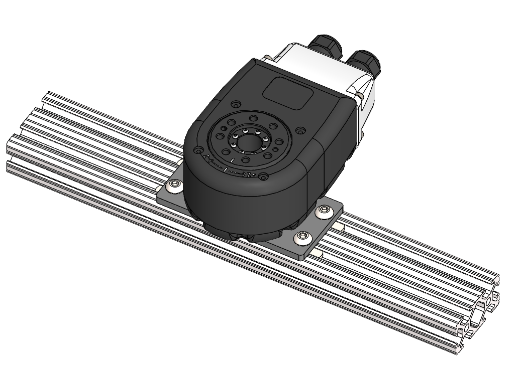
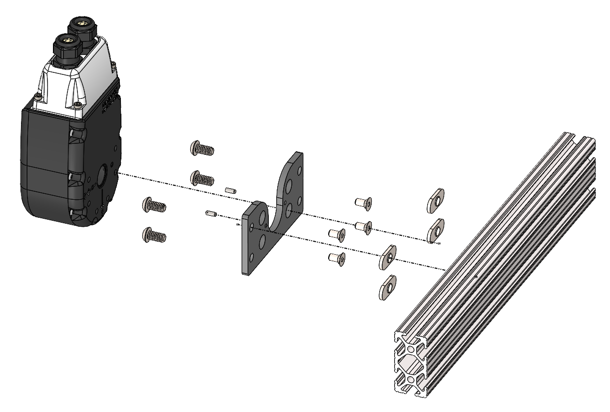
Kinematic Information
T5 / T8 / R8 Actuators
|
|
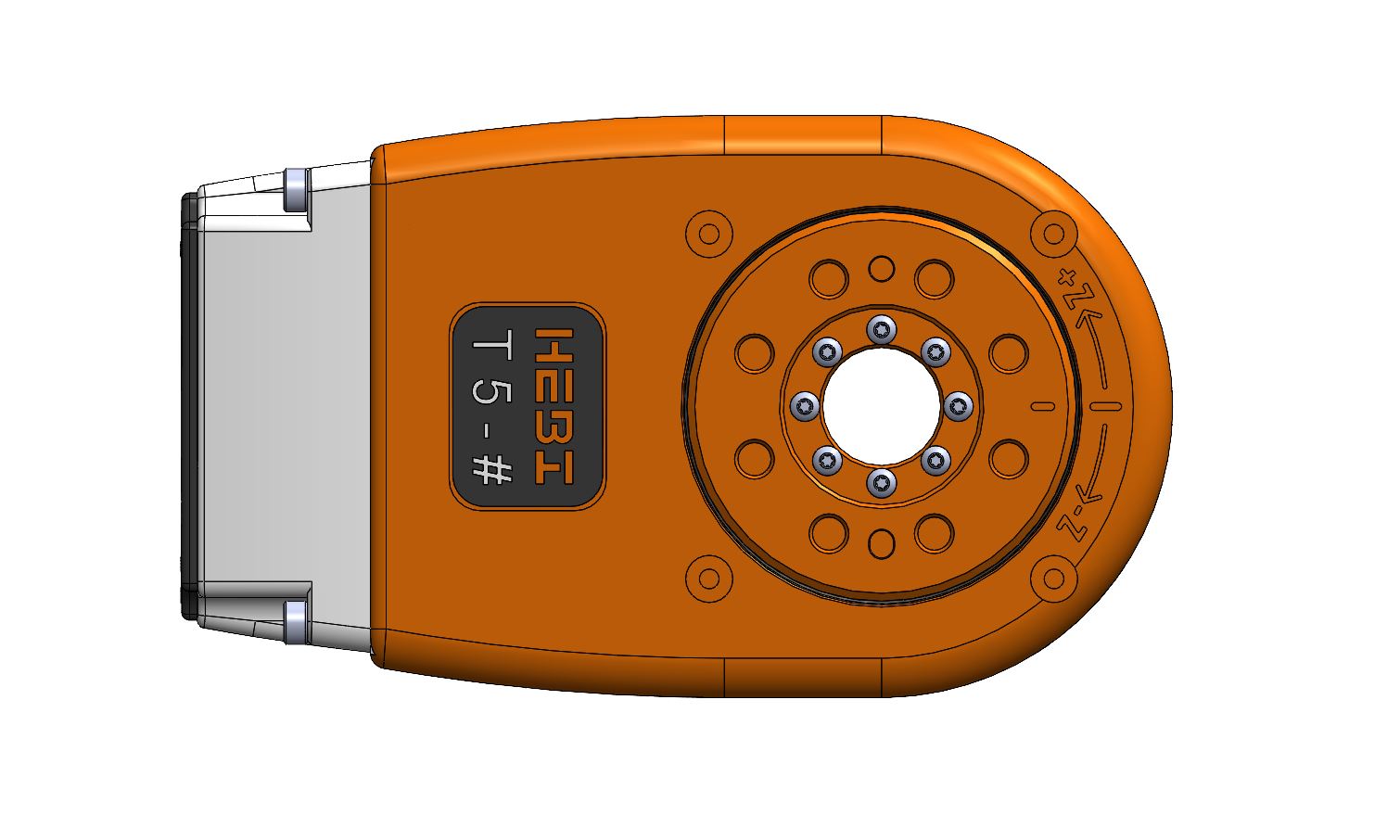
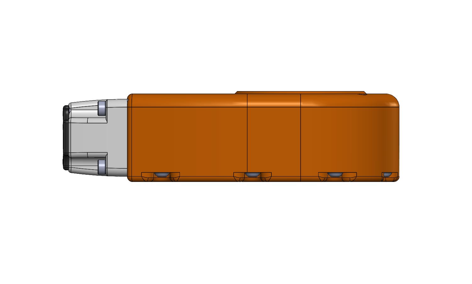
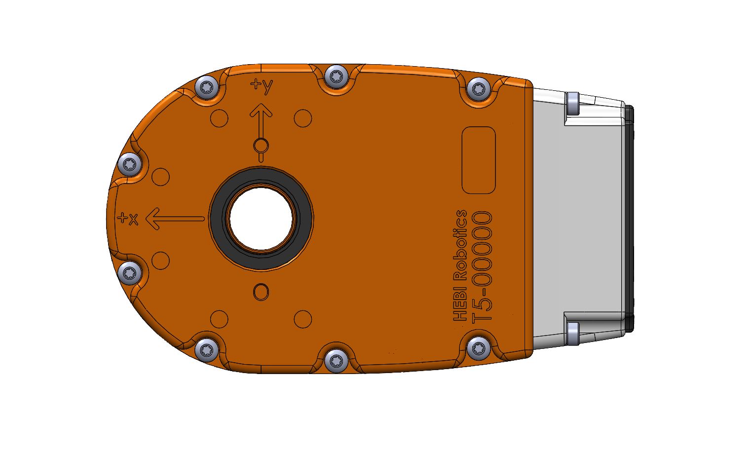
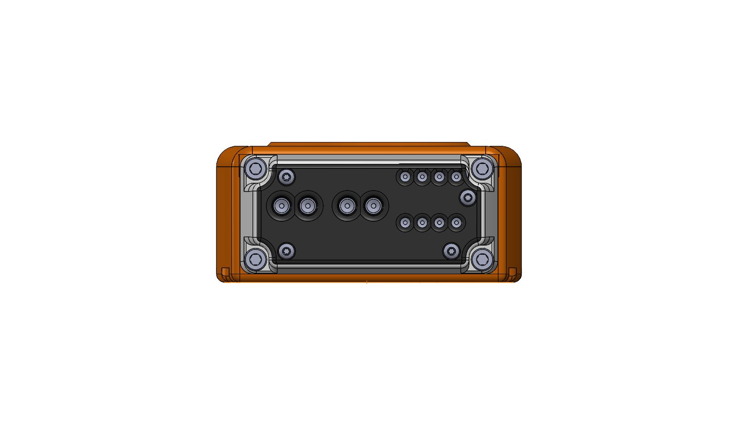
|
|
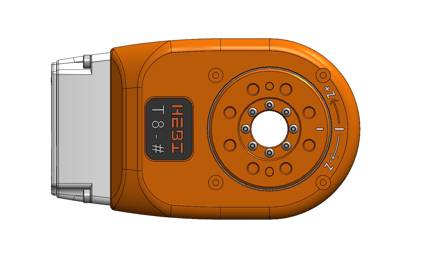
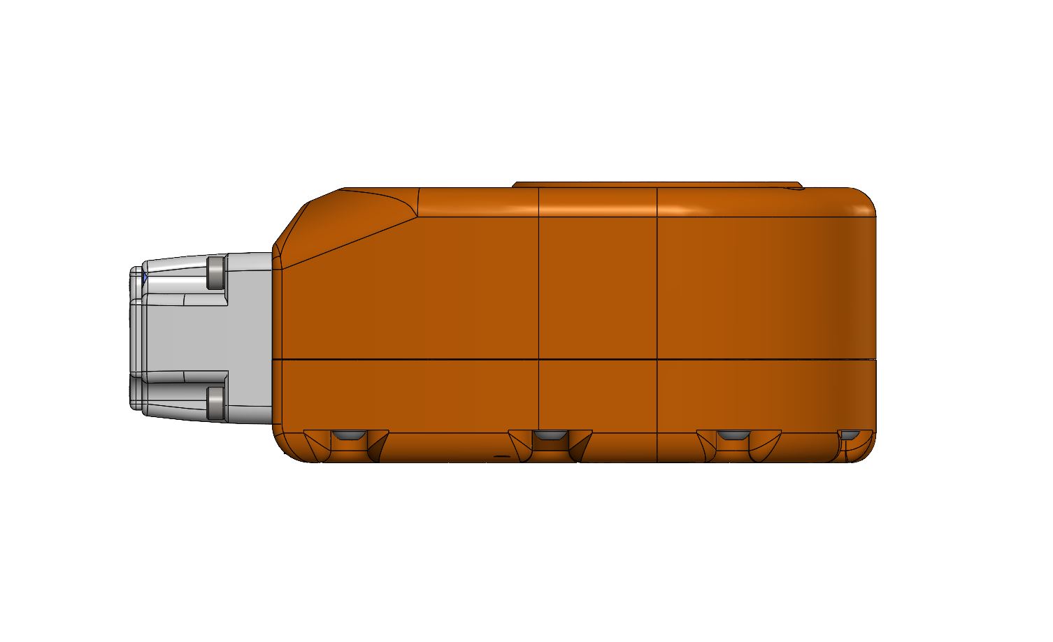
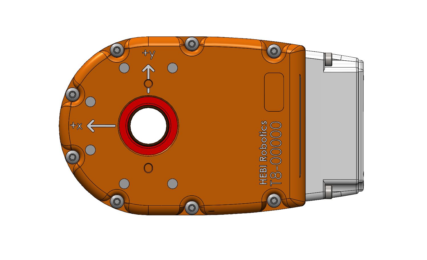
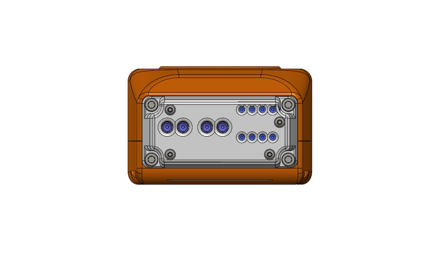
|
|
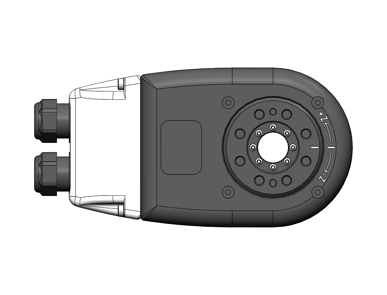
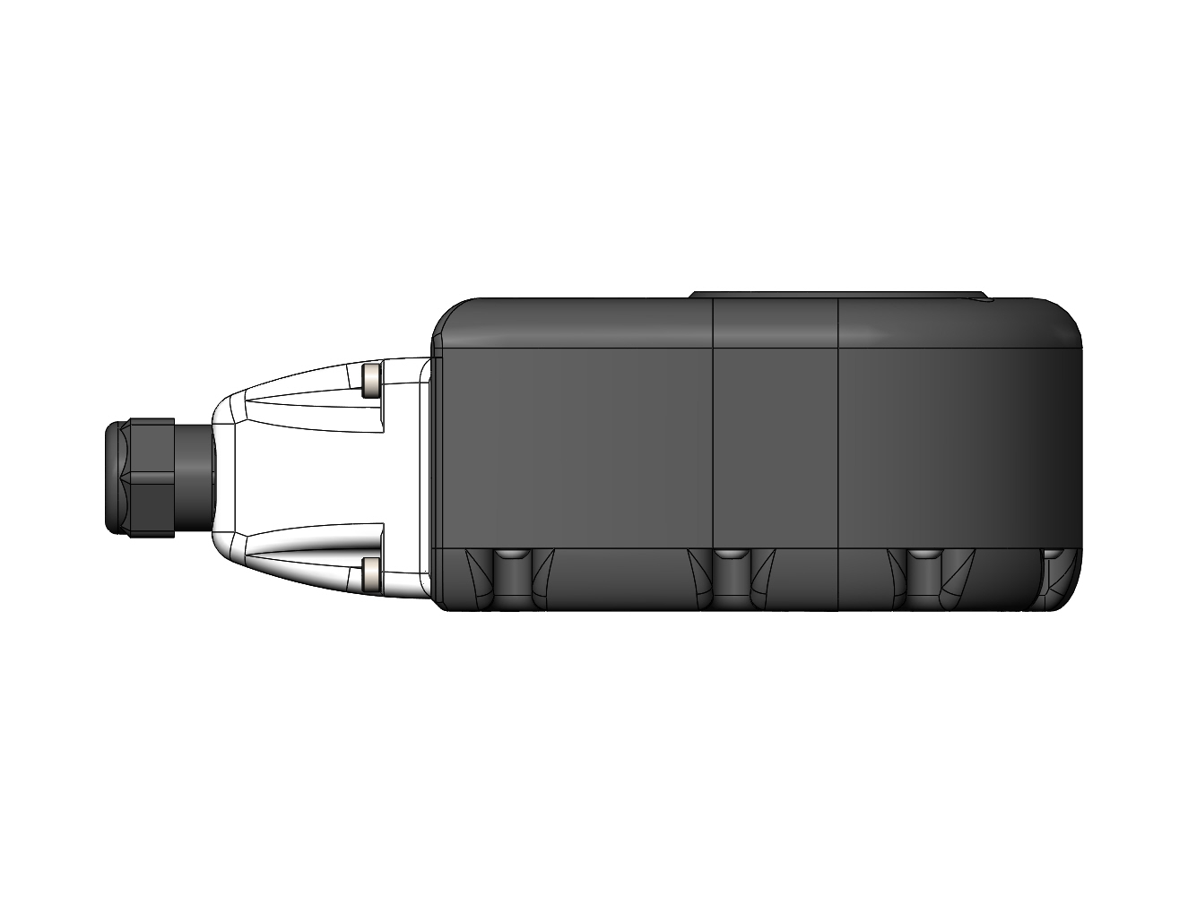
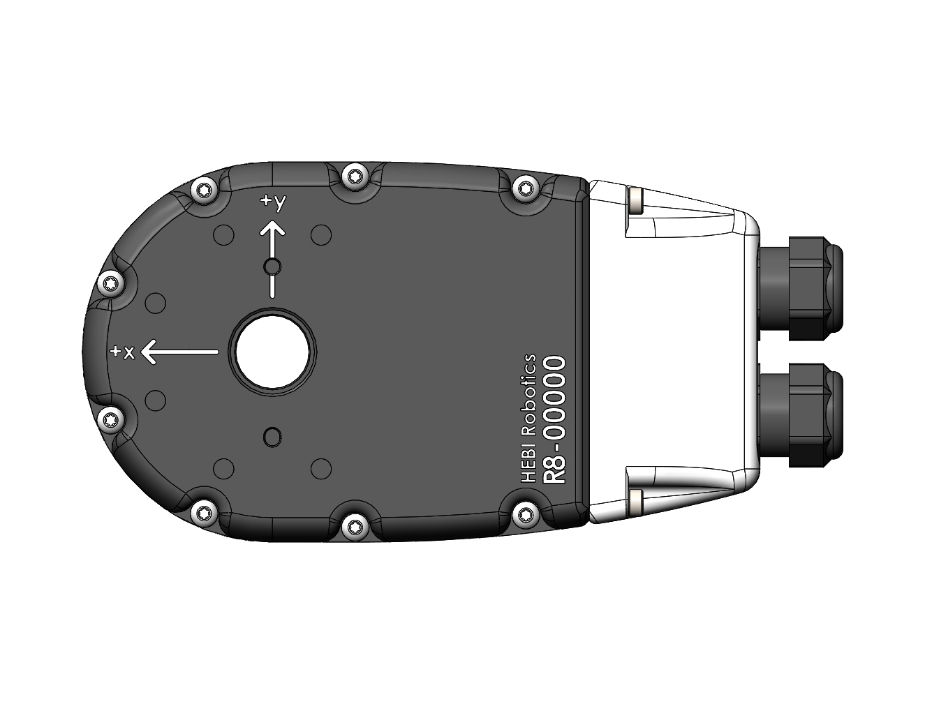
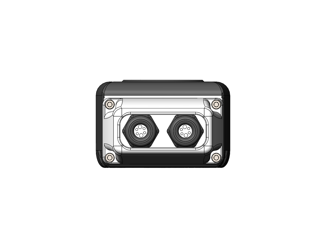
The T-Series and R-Series Actuators all use the same accesories. If this documentation or the HRDF documentation refers to a R-Series Accessory that part can most likely be used on a T-Series Actuator as well.
|
R8 Link
| The R8-Link is very similar to the X5-Link, but is encoded to only fit with R-Series and T-Series parts. The housings of T5, T8, and R8 actuators have the same output interface as X-Series actuators with the addition of M3 dowel pin and slot interfaces, but the housing interface is now actually symmetric about the bore hole where in X-Series actuator the housing bolt pattern has a 2mm offset. |
The R8 Link represents a straight extension that is typically used to connect two R-Series and T-Series actuators. It consists of input and output adapters, as well as a hollow tube that cables can be wired through. It is defined by the extension length as well as the twist angle to the next output.
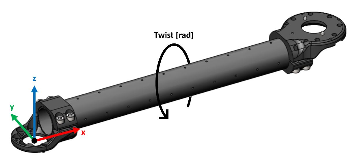

| Parameter | Description |
|---|---|
|
Defined as the center to center distance in meters between rotating axes of the actuator. It is along the X-axis of the link (red axis in the above image). Depending on the type of tube that is being used there are two common ways for calculating the correct distance:
For example, a 300mm tube section has 12 holes, so the total distance would be |
|
Rotation about the X-axis (red axis in the above image). For example, the images above show a twist of PI radians. |
The examples below illustrate the possible variations for the Twist parameter in combination with a 300mm tube (extension=0.325m).
|
|
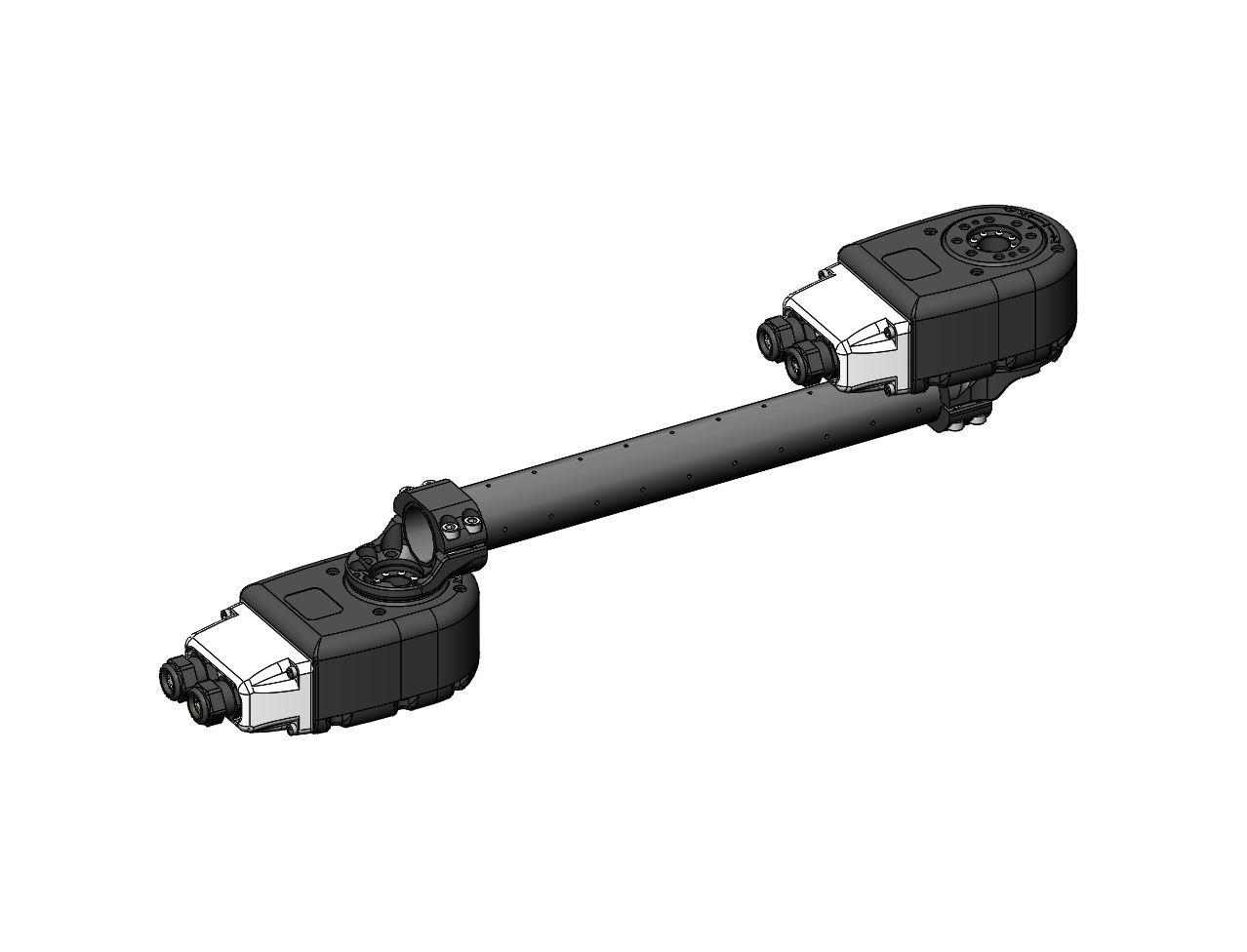
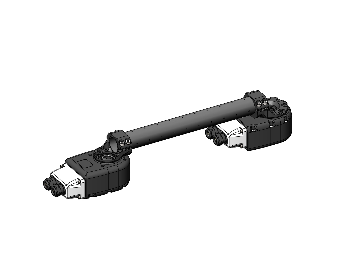
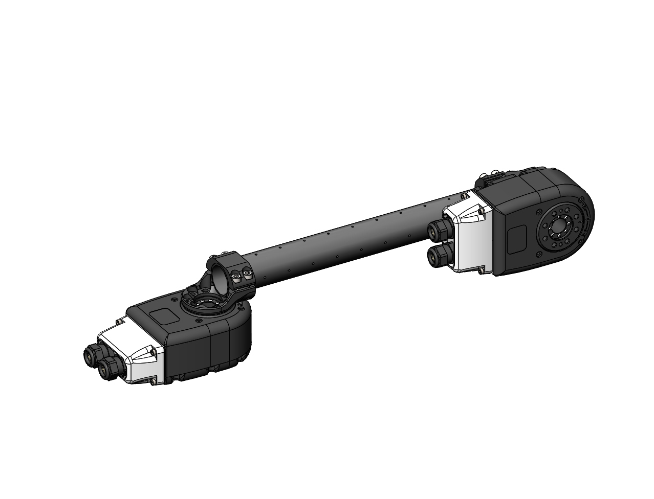
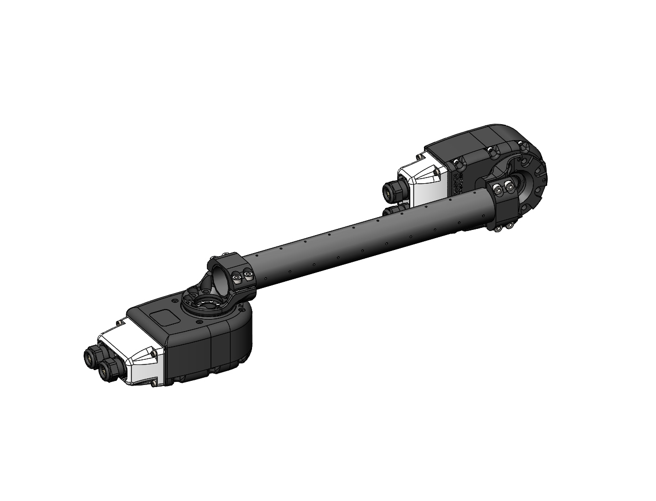
Inline Tube Adapters
An additional attribute for R8 links which is now supported is an inline link adapter for both the output and housing side of actuators. Find out more about these attributes in the HRDF Link format documentation.
|
|
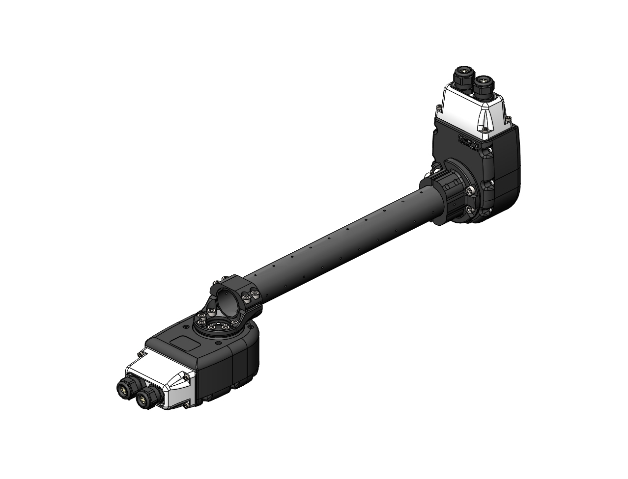
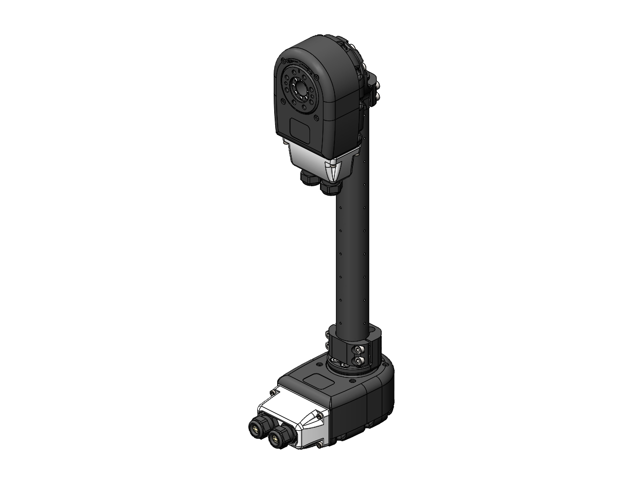
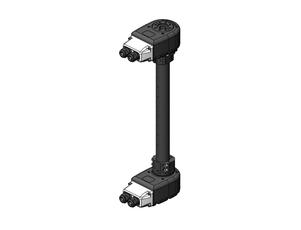
R8 Light Bracket
The R8 Light Bracket corresponds to a light-weight right-angle adapter that is typically used at the wrist of an arm. It has a single parameter that specifies the mounting direction.
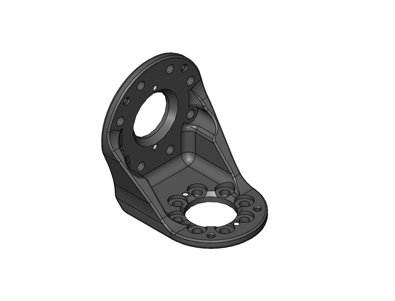
| Parameter | Description |
|---|---|
|
The direction of the output 'Z' axis (blue) pointing towards the next module, assuming that the 'X' axis (red) is pointing forward and the position is zero. The two possible configurations are:
|
Note that the left and right configurations are the same part mounted in a different orientation.
|
The below images show both mounting configurations at an output position of zero.
Part Number: A-2220-01 |
Part Number: A-2220-01 |
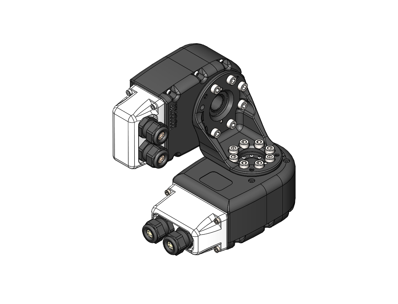
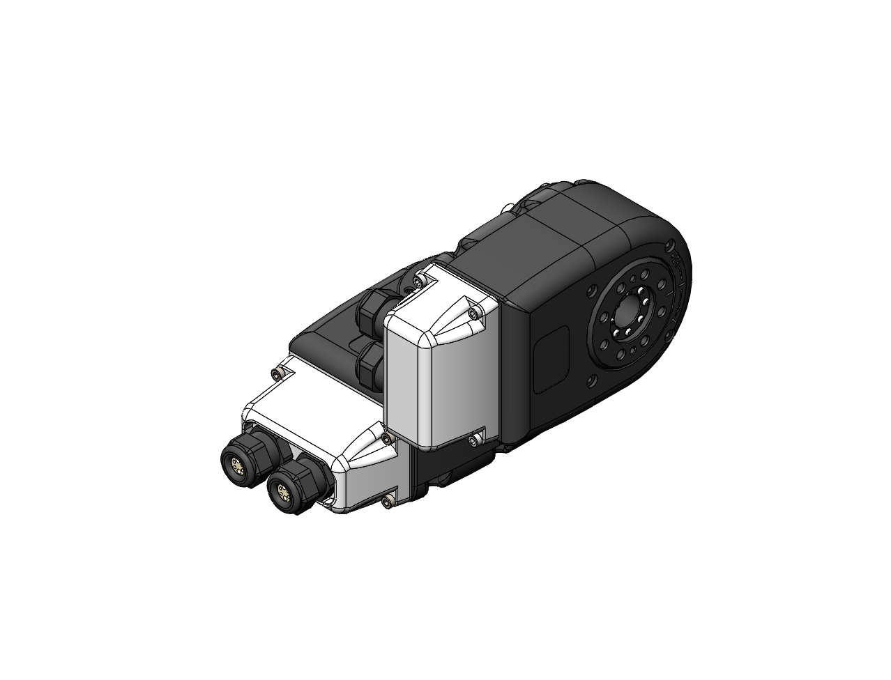
R8 Heavy Bracket
The R8 Heavy Bracket type corresponds to a sturdy right-angle adapter that is typically used at the base of a robot arm configuration. It has a single parameter that specifies the mounting direction.
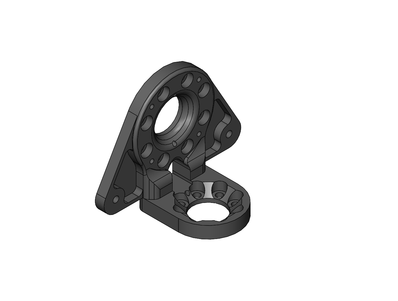
| Parameter | Description |
|---|---|
|
Due to the modular design of the bracket there are four different configurations. This parameter describes the output direction (same as the light bracket above) as well as the mounting side (closer or further away from the center). The four possible configurations are
|
Note that the left vs right portion of the configurations are the same part with a symmetric gas spring mounting, and the inside vs outside portion of the configuration describe the two different ways a given bracket can be assembled.
|
The below images show the four possible mounting configurations at an output position of zero.
Part Number: A-2221-01 |
Part Number: A-2221-01 |
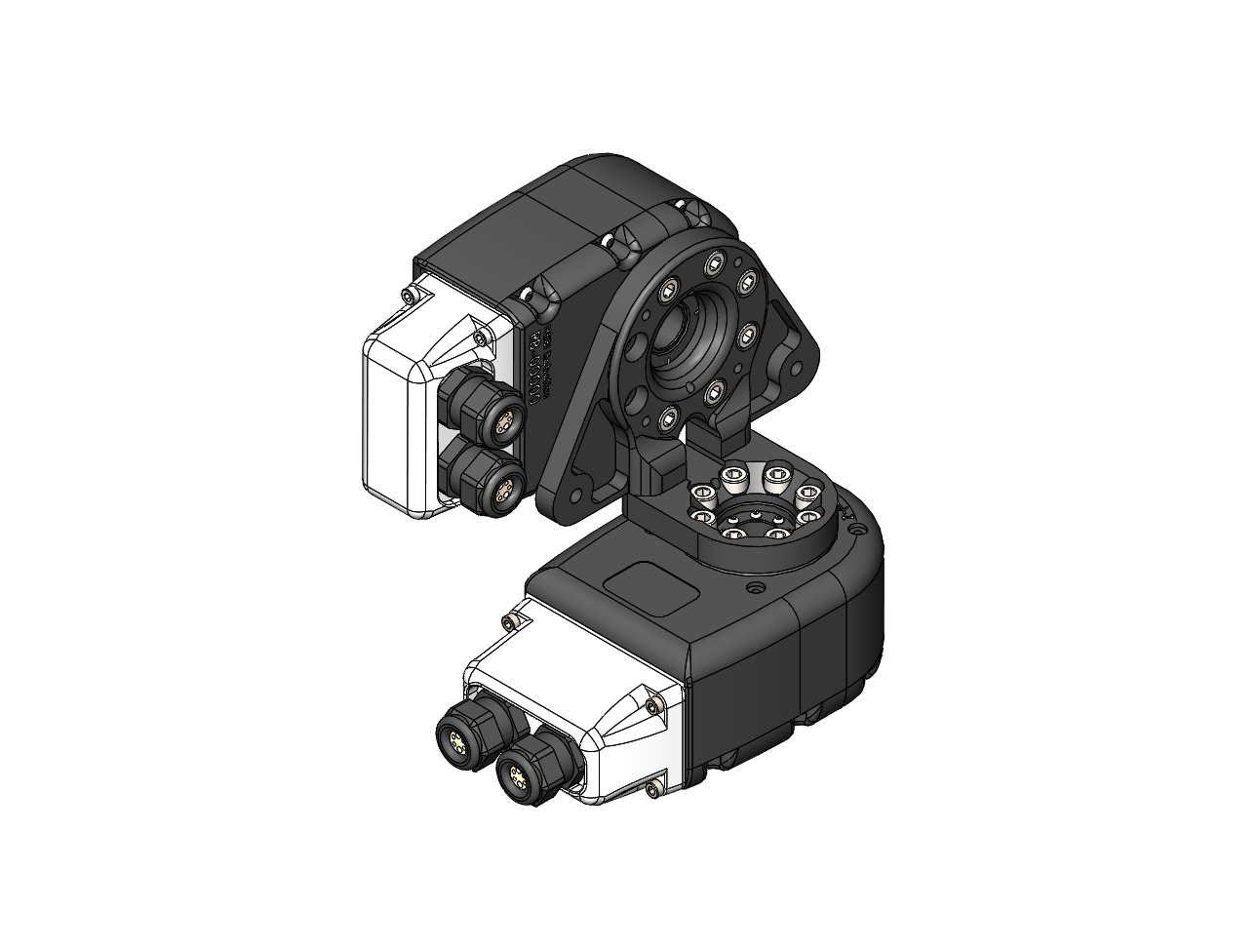
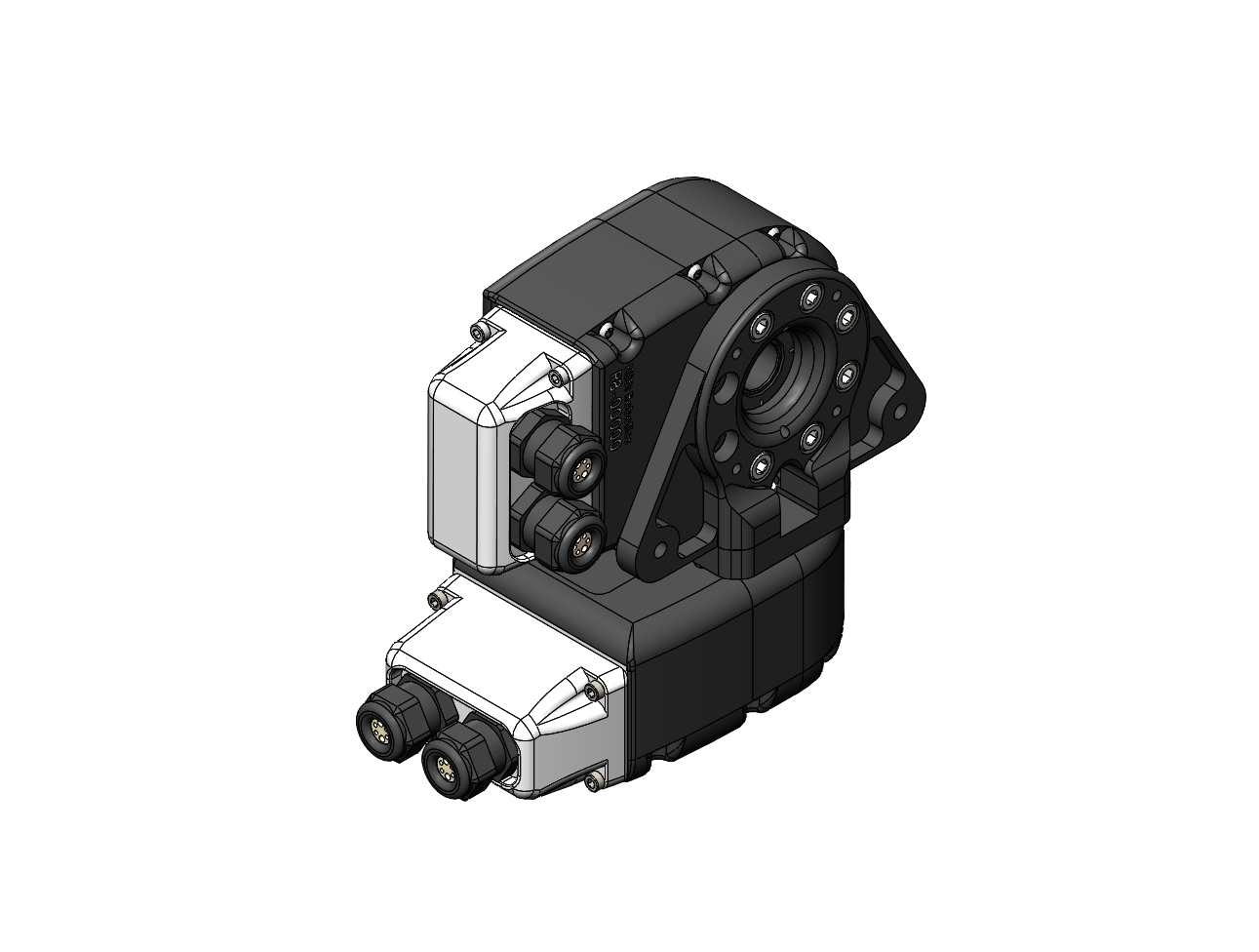
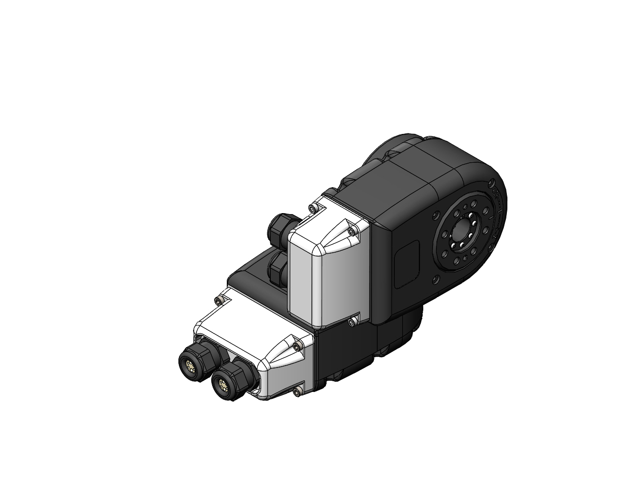
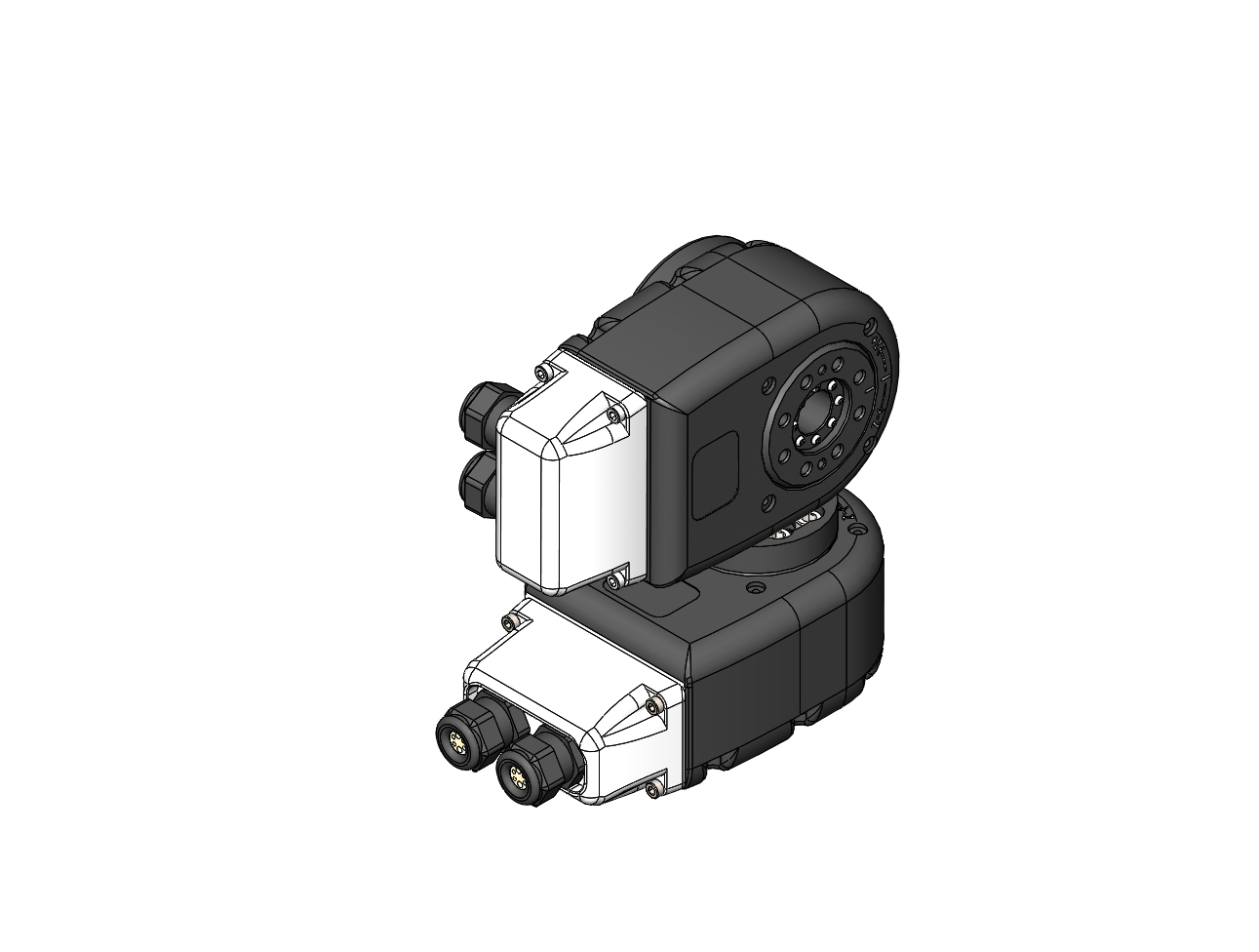
X5 and X8 Actuators
| The X-Series Actuators are Discontinued. |
|
|
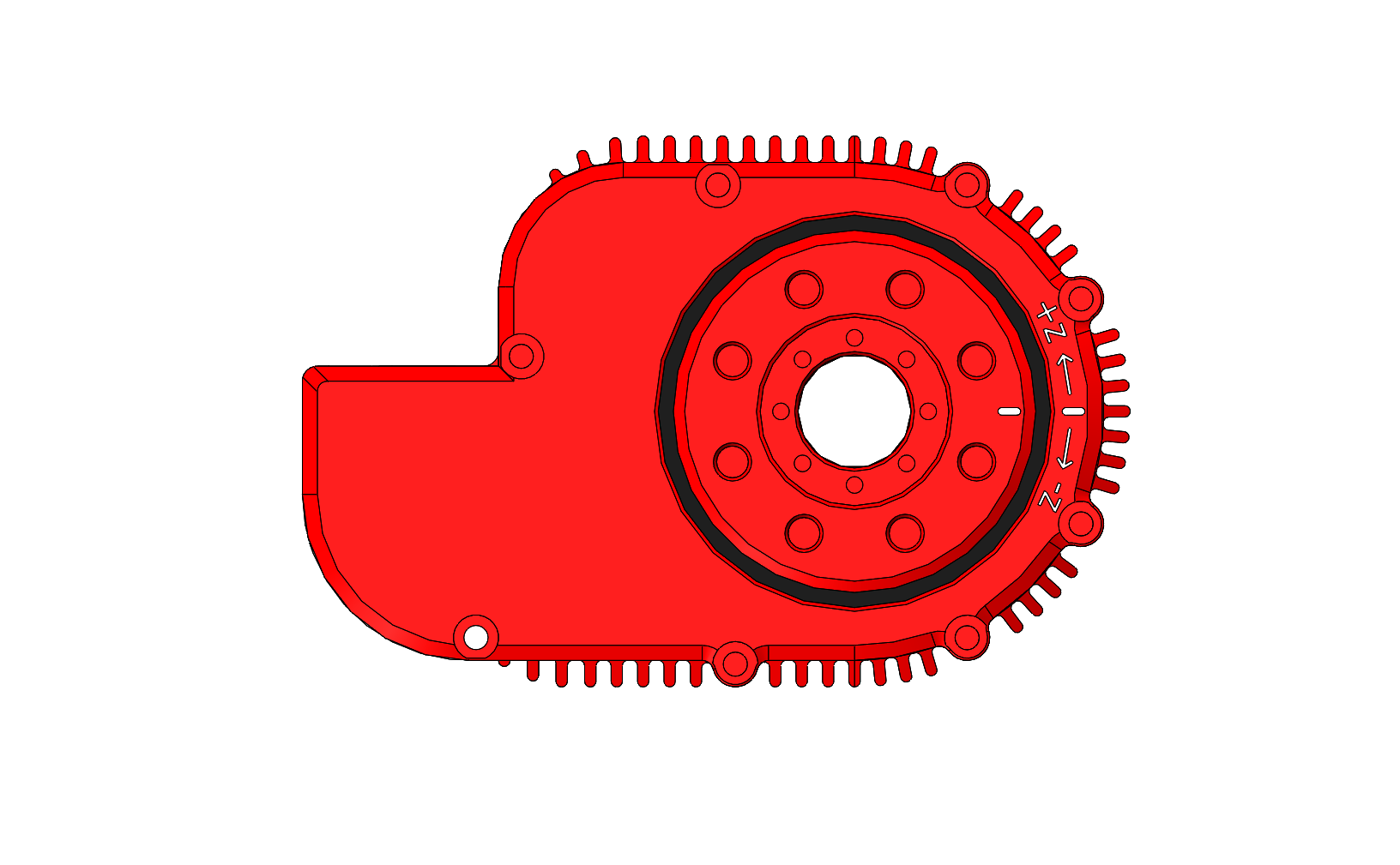
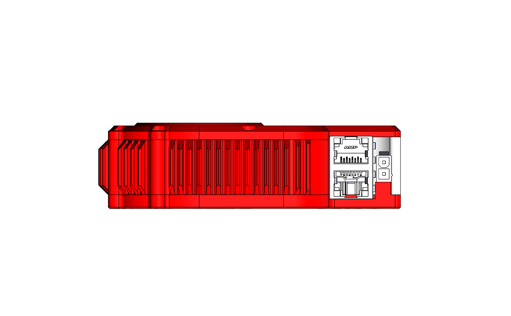
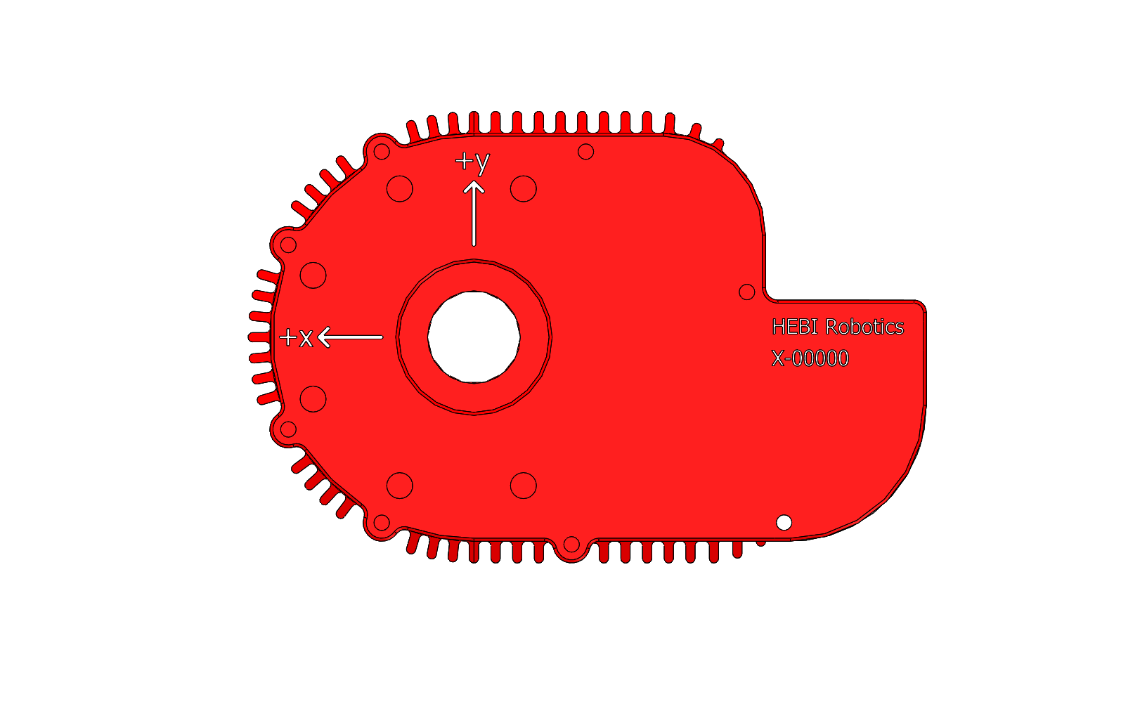
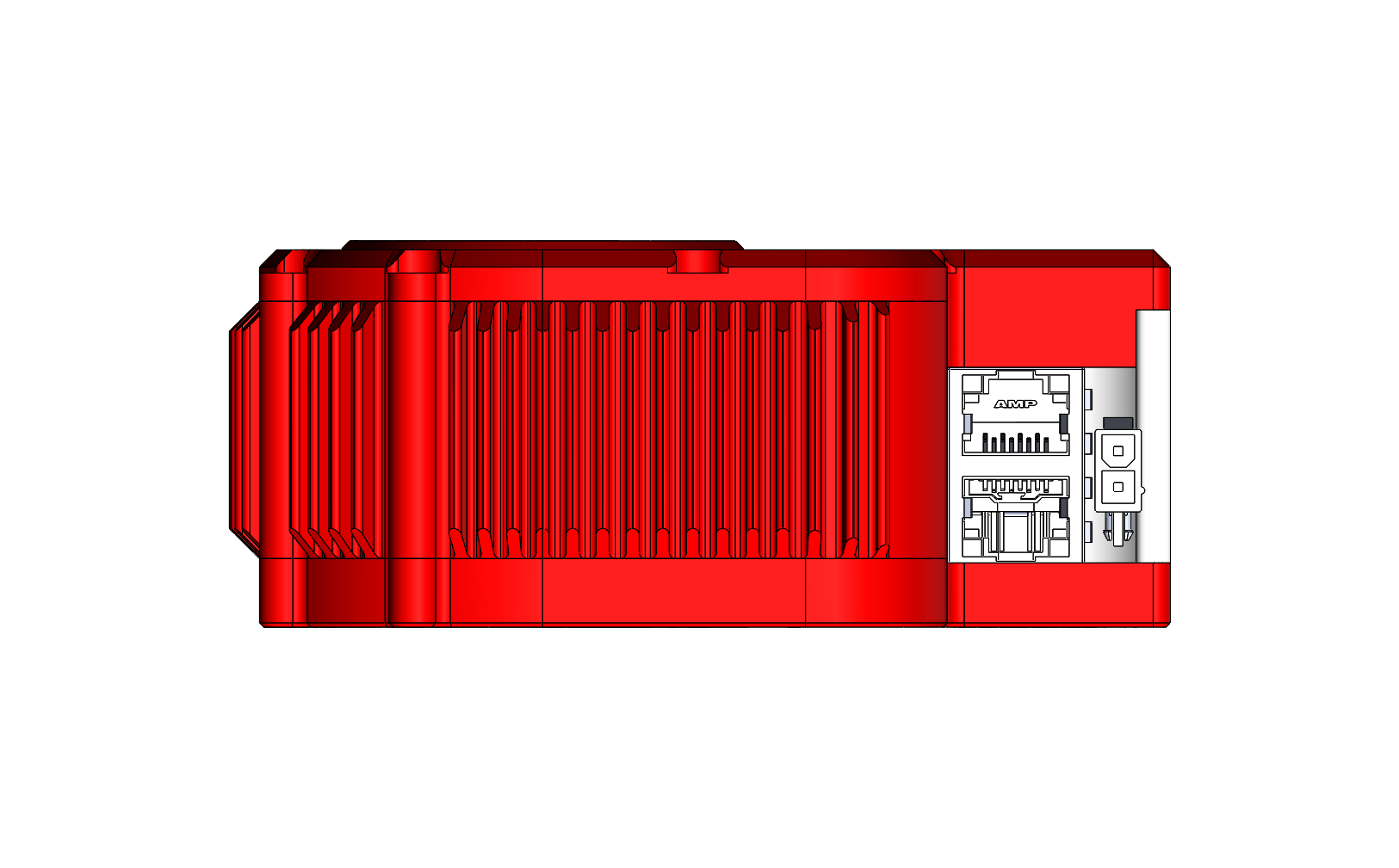
X5 Link
| There are no dedicated X8-Link or X8-Bracket parts. The housings of X5 and X8 actuators have the same input and output interface, so the X8 actuators are compatible with X5 connection parts. |
The X5 Link represents a straight extension that is typically used to connect two X-Series actuators. It consists of input and output adapters, as well as a hollow tube that cables can be wired through. It is defined by the extension length as well as the twist angle to the next output.
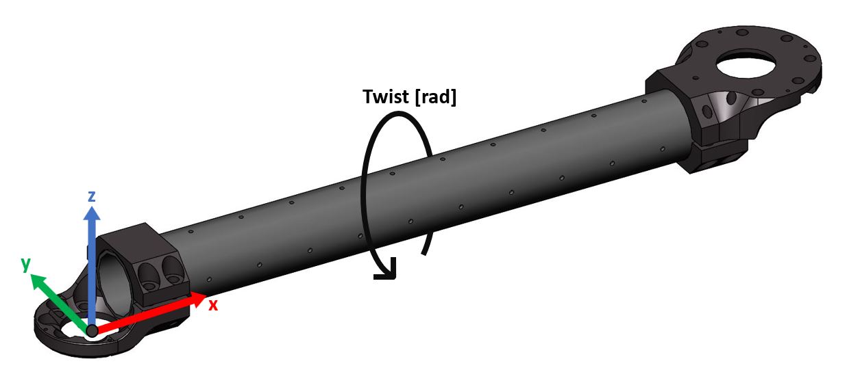

| Parameter | Description |
|---|---|
|
Defined as the center to center distance in meters between rotating axes of the actuator. It is along the X-axis of the link (red axis in the above image). Depending on the type of tube that is being used there are two common ways for calculating the correct distance:
For example, a 300mm tube section has 12 holes, so the total distance would be |
|
Rotation about the X-axis (red axis in the above image). For example, the images above show a twist of PI radians. |
The examples below illustrate the possible variations for the Twist parameter in combination with a 300mm tube (extension=0.325m).
|
|
Inline Tube Adapters
An additional attribute for X5 links which is now supported is an inline link adapter for both the output and housing side of actuators. Find out more about these attributes in the HRDF Link format documentation.
| Input is defined as the proximal adapter to the link, whereas Output is defined as the distal adapter to the link. |
|
|
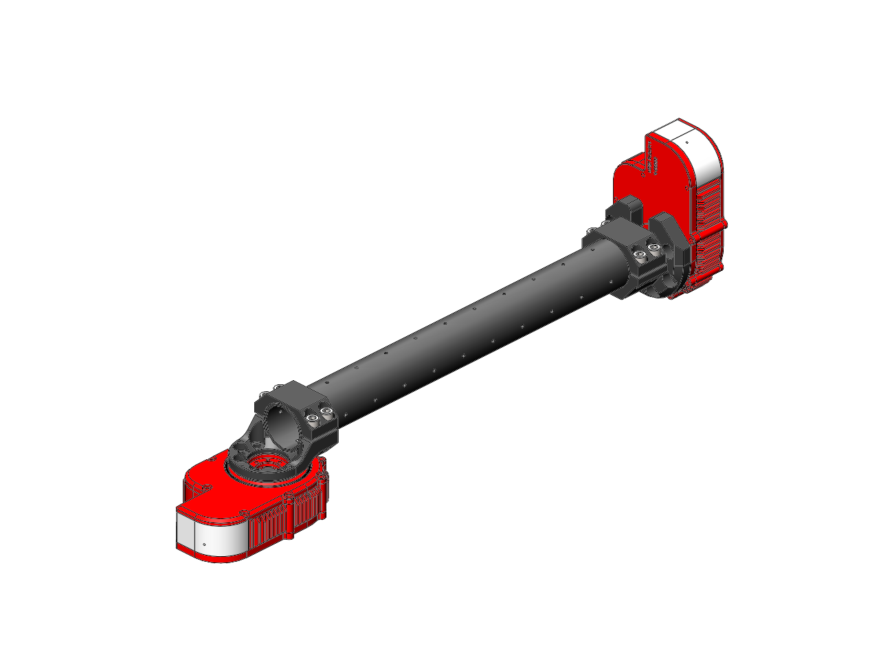
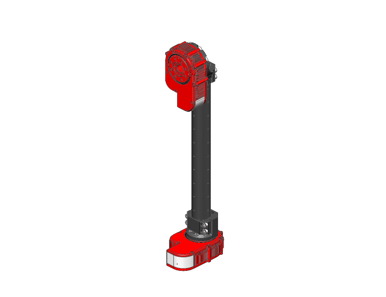
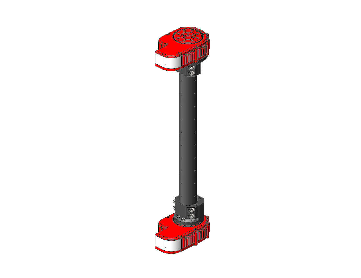
X5 Light Bracket
The X5 Light Bracket corresponds to a light-weight right-angle adapter that is typically used at the wrist of an arm. It has a single parameter that specifies the mounting direction.
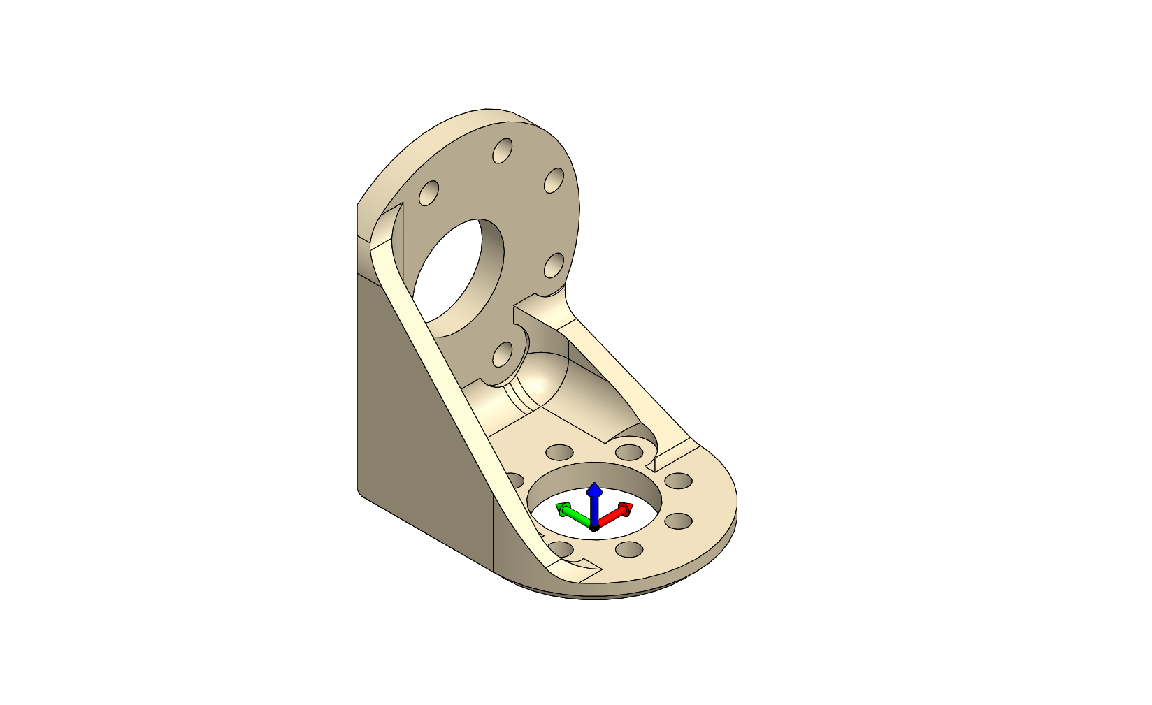
| Parameter | Description |
|---|---|
|
The direction of the output 'Z' axis (blue) pointing towards the next module, assuming that the 'X' axis (red) is pointing forward and the position is zero. The two possible configurations are:
|
Note that the left and right configurations are physically different parts, rather than the same part mounted in a different orientation.
|
The below images show both mounting configurations at an output position of zero.
Part Number: A-2042-01L |
Part Number: A-2042-01R |
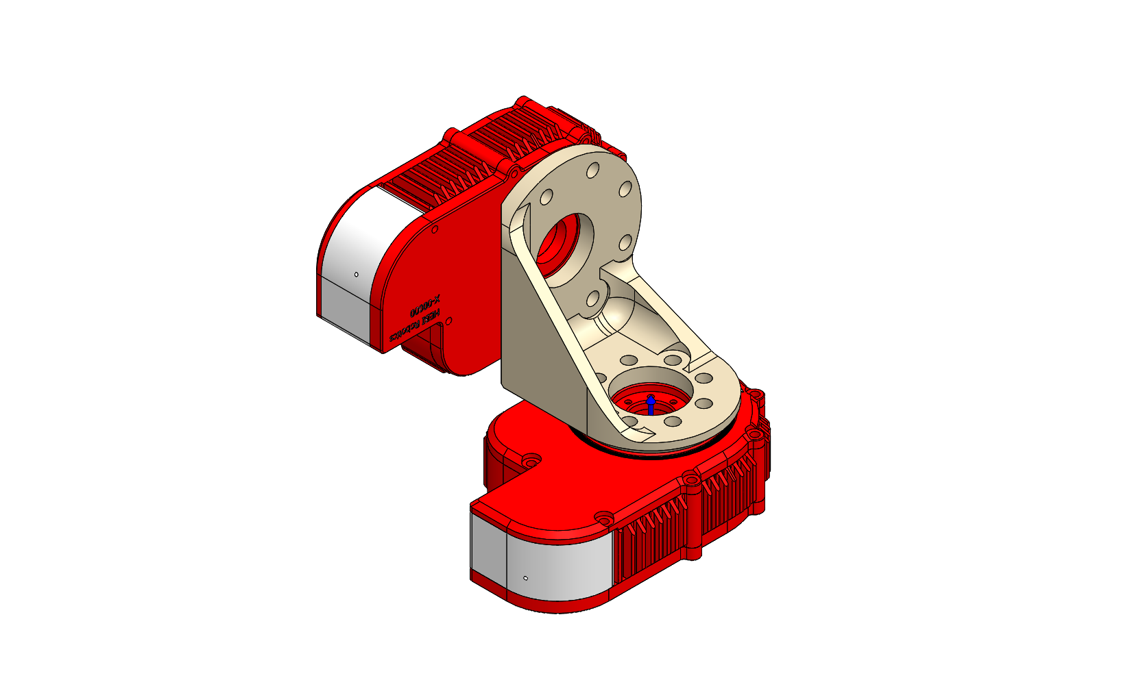
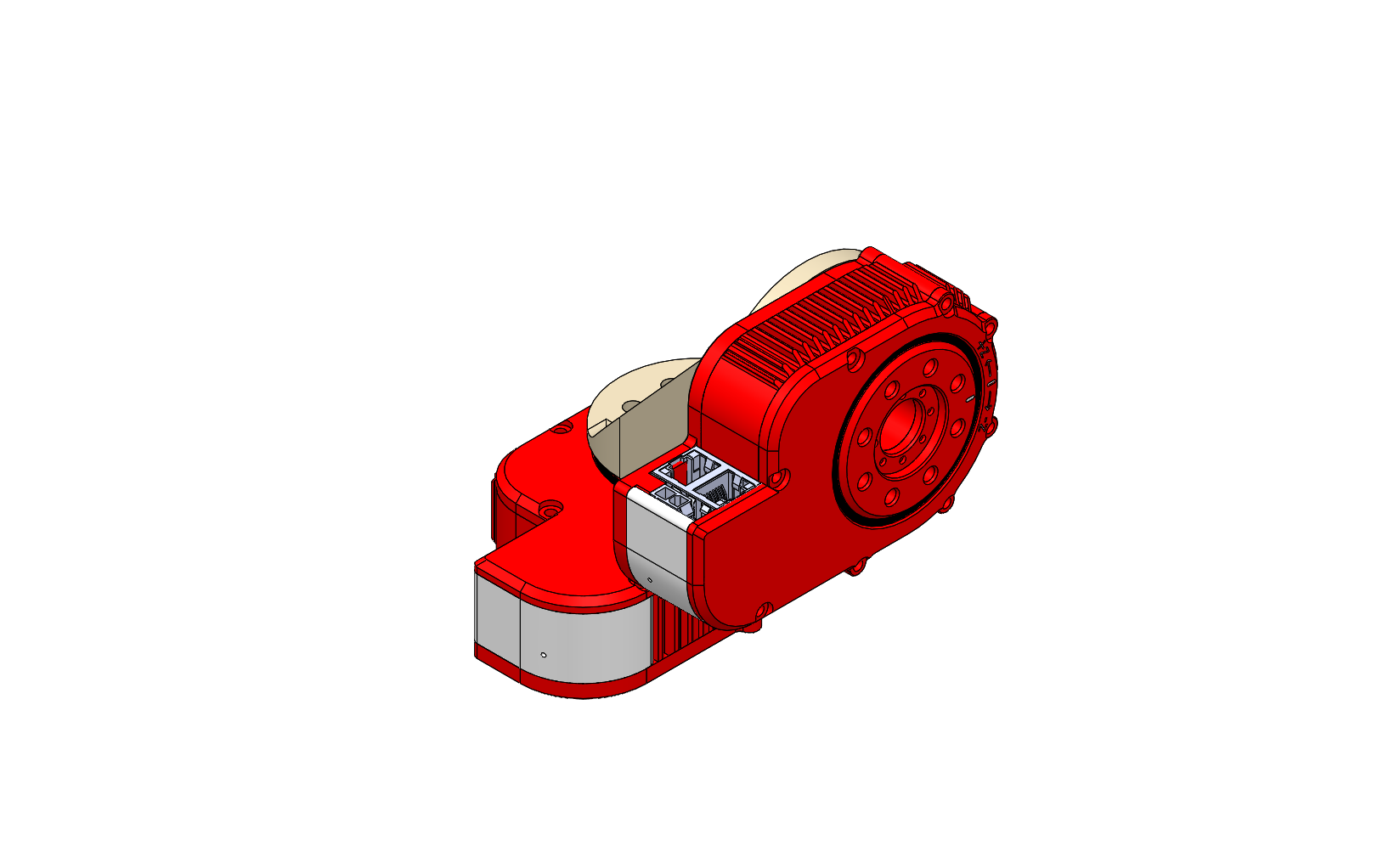
X5 Heavy Bracket
The X5 Heavy Bracket type corresponds to a sturdy right-angle adapter that is typically used at the base of a robot arm configuration. It has a single parameter that specifies the mounting direction.
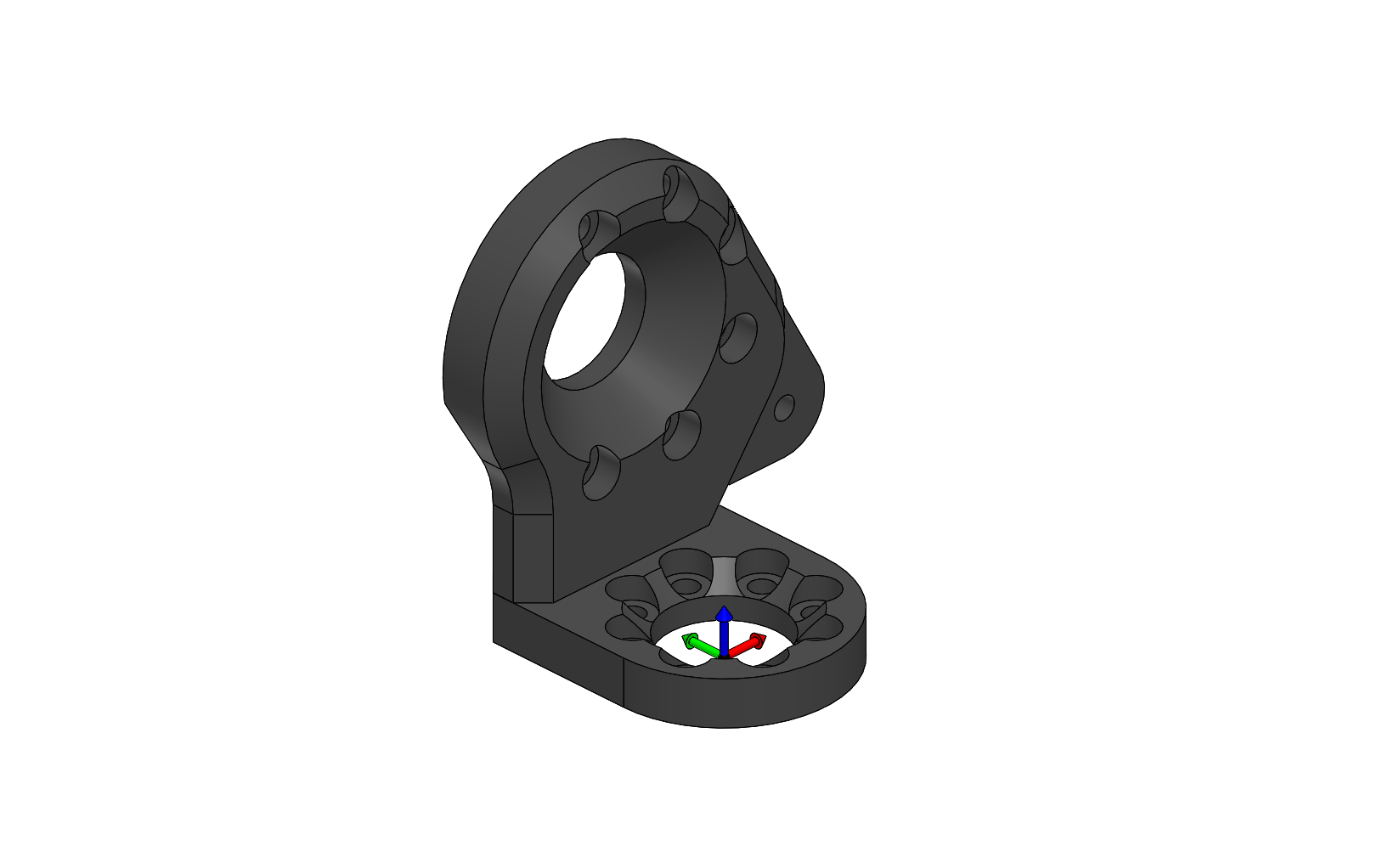
| Parameter | Description |
|---|---|
|
Due to the modular design of the bracket there are four different configurations. This parameter describes the output direction (same as the light bracket above) as well as the mounting side (closer or further away from the center). The four possible configurations are
|
Note that the left vs right portion of the configurations are physically different parts, and the inside vs outside portion of the configuration describe the two different ways a given bracket can be assembled.
|
The below images show the four possible mounting configurations at an output position of zero.
Part Number: A-2040-01L |
Part Number: A-2040-01R |