Overview

HEBI provides modular robotic building blocks that let you build and program custom robotic systems quickly. We provide physical actuators, digital and analog interface boards, and the mechanical and electrical hardware to connect these components together (see our hardware documentation).
Just as important as the hardware, HEBI also provides software tools and APIs to program and control the robotic system created from these physical components.
Start with one of the following options to get started with your HEBI components:
-
Run through the one of the Quickstart Guides to hook up and move an actuator, no programming required.
-
Start with one of the customizable HEBI kits complete with example code (Python / C++ / MATLAB) to hit the ground running, and then modify to suit your needs.
-
Pick your favorite programming language and get started with our code examples:
-
Jump into the full tutorial and documentation for each API for more information and advanced concepts:
Quickstart Guides
H-Series Actuator
| The H-Series Actuators are electrically compatible with our R/T-Series Actuators so this guide will look similar to the R/T-Series Actuator Quickstart Guides. |
Getting Started
The following instructions are meant to get you up and running quickly if you are new to HEBI H-Series actuators. If you have any questions please:
-
Check the full online documentation at http://docs.hebi.us
-
Contact us at support@hebirobotics.com.
Connection Toolbox
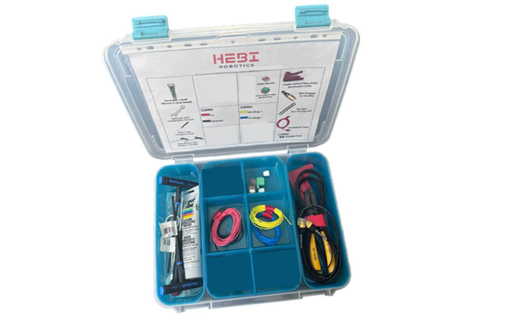
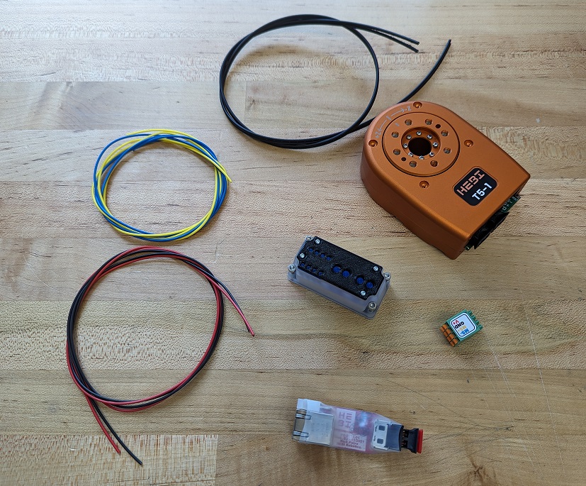
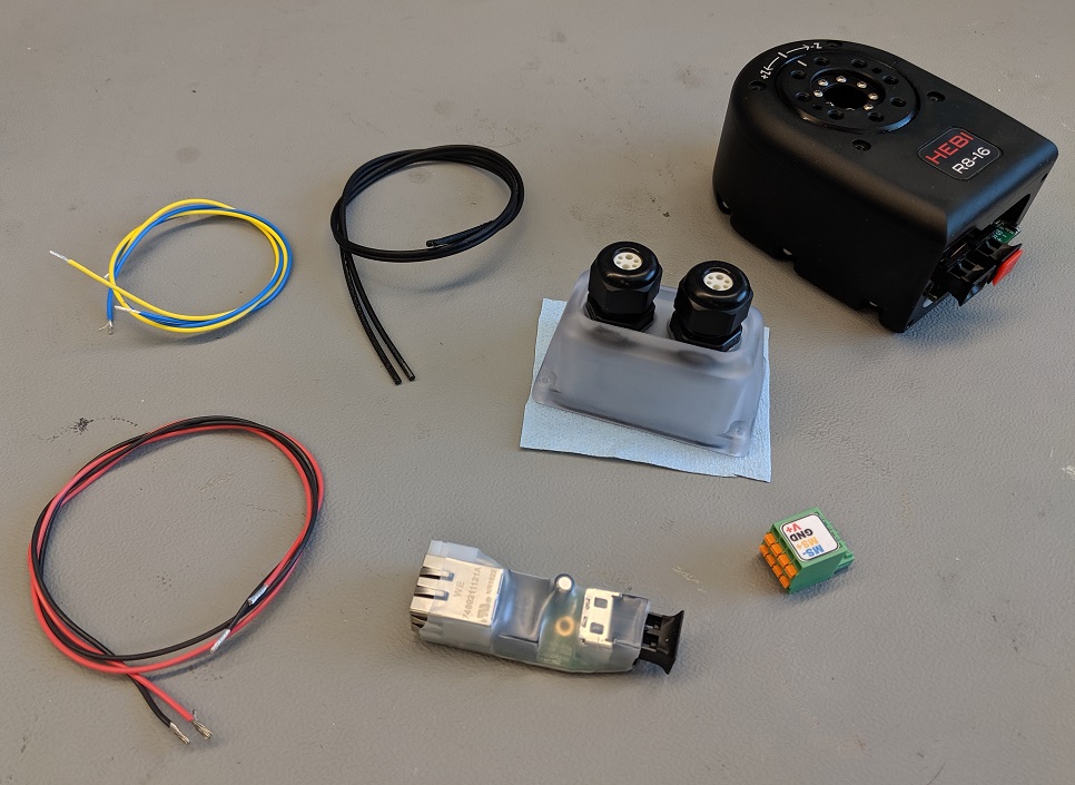
This H-Series Connection Toolbox contains all of the necessary tools, wiring, and extra supplies to work with the H-Series Actuators. A complete Bill of Materials can be found here: Connection Toolbox BOM
Download the Scope GUI
Go to docs.hebi.us and get the latest version of the Scope GUI for your computer (Windows, macOS, Linux).
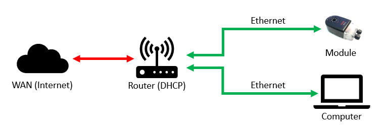
Wiring Block Diagram
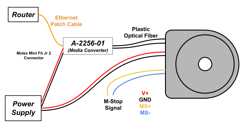
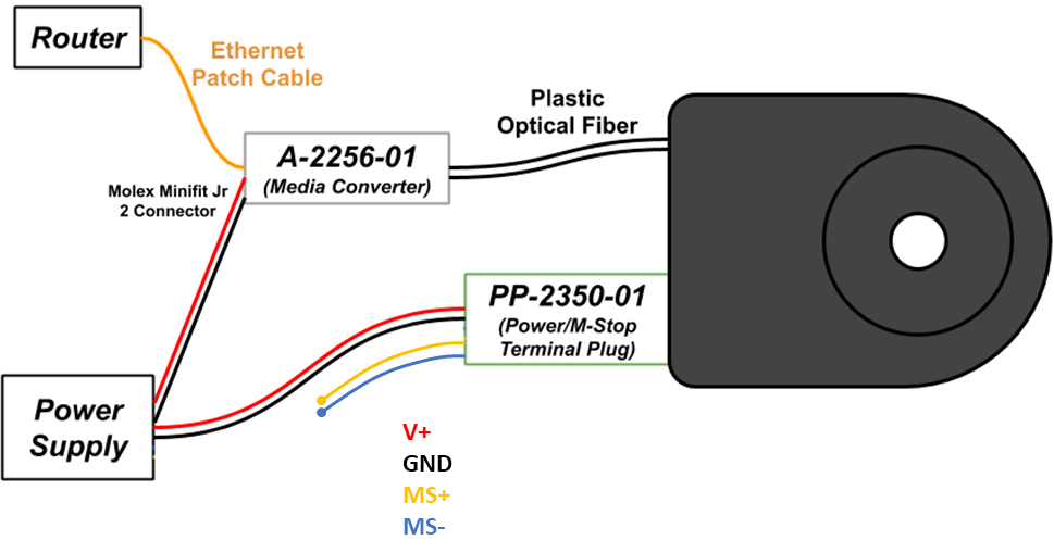
Here is a simple Block Diagram showing the wiring setup for the H-Series Actuator. All electronics shall be used with a 24-48V power supply. The communication is 100 Mbps Ethernet converted in the Media Converter from and RJ45 connection to Plastic Optical Fiber into the Actuator. Power, Ethernet, and M-Stop can daisy-chain between actuators.
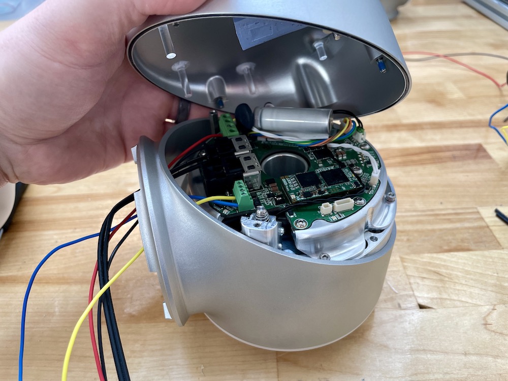
Unscrew and Remove the Actuator Cap


Use a 2.5mm hex driver to remove the captive screws in the actuator cap. Lift the cap gently straight up away from the main PCB. If the IO Micro daughterboard sticks the cap thermal pad, and comes off the main PCB during this step, carefully reseat it.


Trimming and Splitting Duplex Fiber Cables
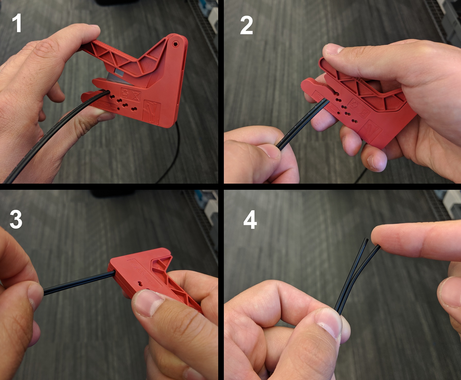
The Plastic Optical Fiber (POF) comes in single strand and duplex paired strands. Use the PP-2402-01 (POF Termination Cutter) provided in the Toolbox to cut the cables and also to split the duplex pair in order to pass thru the sealing Cord Grips and install in the fiber connectors.
Connect Media Converter
-
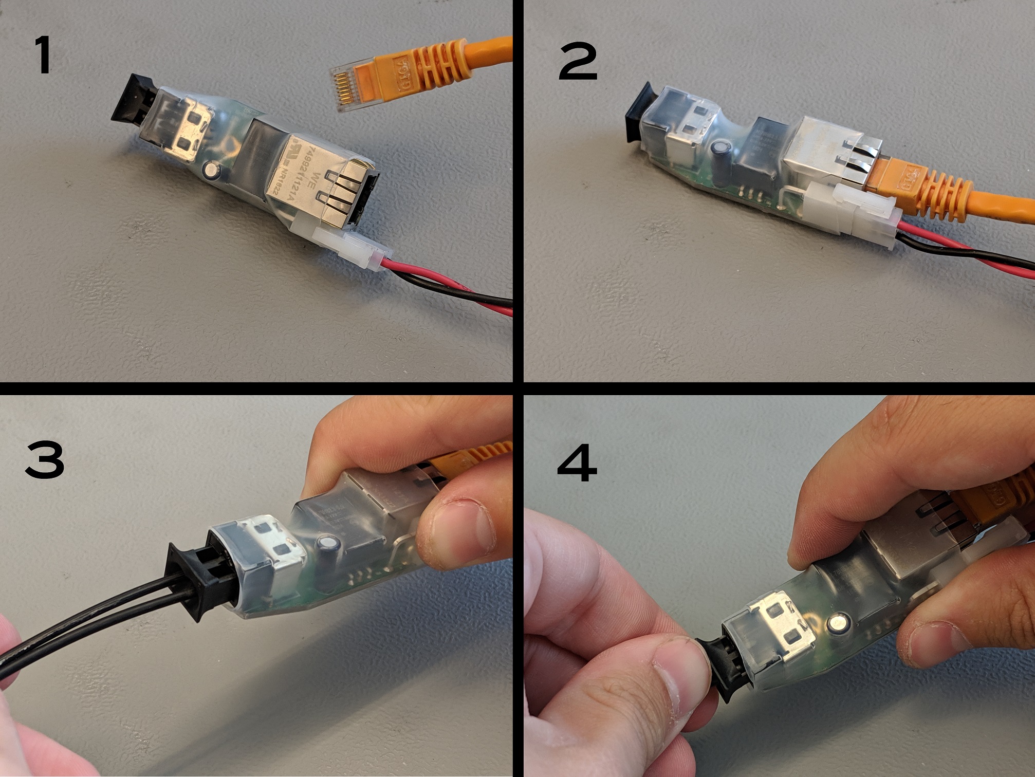
Take the A-2256-01 (Fiber-Ethernet Media Converter) and connect a power cable with a Molex Minifit Jr connector.
-
Use an Ethernet cable to connect the Media Converter to a router or switch on your local area network (LAN).
-
Pull the outer piece of the Fiber Connector outwards and install the end of the Fiber cables into the connector.
-
Push the outer piece of the Fiber Connector inwards as to hold the Fiber cable in place.
Turn On Power
Connect the other ends of the power cables to a power source. Turn on the power supply, or connect/activate batteries. The actuators run on any DC voltage source between 36V-48V. The Status LED will start blinking green/orange while the actuator is trying to obtain an IP address. One of the fiber cables will have a bright red light coming thru it.
| An H-Series Actuator can draw up to 500W at peak power, but draws less than 2W at idle. Typical continuous power draw for most applications is much lower than the peak power draw, usually 50W-100W. It is important to choose an appropriate power supply for your application. See the Power section of the online documentation for more information. |
Connect Fiber Ethernet
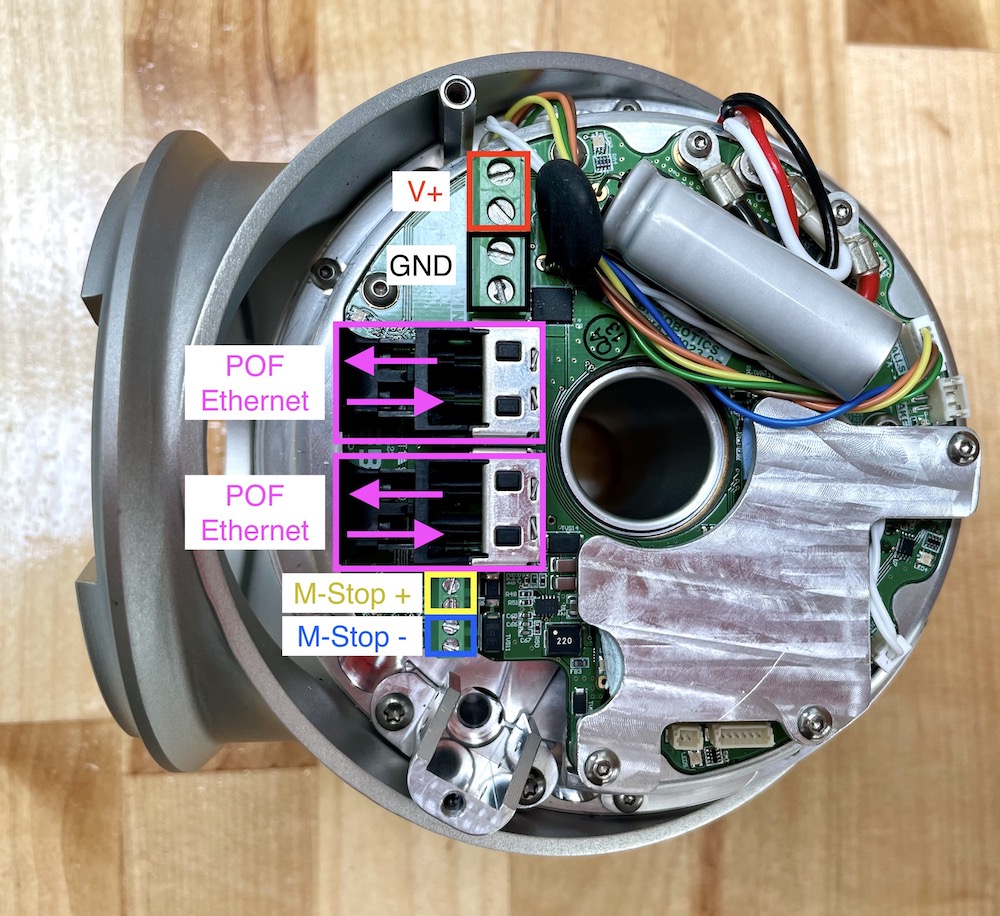
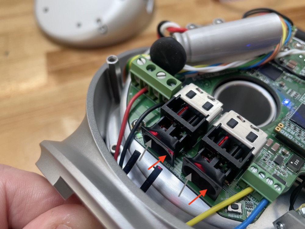
The optical connectors on the actuator should have a red light coming out from one of the two receptacles. The optical fiber with the red light shining thru it should go into the port that has no light coming from it and vice-versa.
Actuators ship by default configured to run on DHCP. This means that to work correctly there needs to be a router on the network configured for DHCP. There are methods for setting a Static IP address if no router is available.
| It is important to use a wired ethernet connection between your computer and actuators for maximum reliability. A wireless connection will sometimes work, and is generally still useful for viewing feedback in the Scope GUI. However, there potentially be packet loss and increased latency that may cause issues with motor control. |
Wiring Direction and Daisy-Chaining


The wiring into the actuator can come either from the fixed side of the housing, or up thru the rotating output, depending on how the actuator is going to be mounted and used. Additional actuators can also be connected in series, running the wires thru the hollow board in the center of the actuator.


Re-Install the Actuator Cap
Set the cap carefully back onto the actuator. Make sure no wires are protruding, or caught under the thermal pad that rests on the IO Micro board. Use a 2.5mm hex driver to remove the captive screws in the actuator cap.
Restart Power
Turn off and turn back on actuator power. Again, the Status LED will start blinking green/orange while the actuator is trying to obtain an IP address. After a few seconds, the LED will change to a slow green fade. Once the actuator is in this state it will respond to commands and provide feedback from its internal sensors.
| If the actuator does not get an IP address, make sure that your network has a router configured for DHCP. Some corporate and institutional networks may also have network security features set up that can interfere with DHCP and/or UDP broadcast, which can create cases where actuators are assigned IP addresses but will not be visible in Scope or the APIs. If you suspect this is the case please talk with your network administrator. |
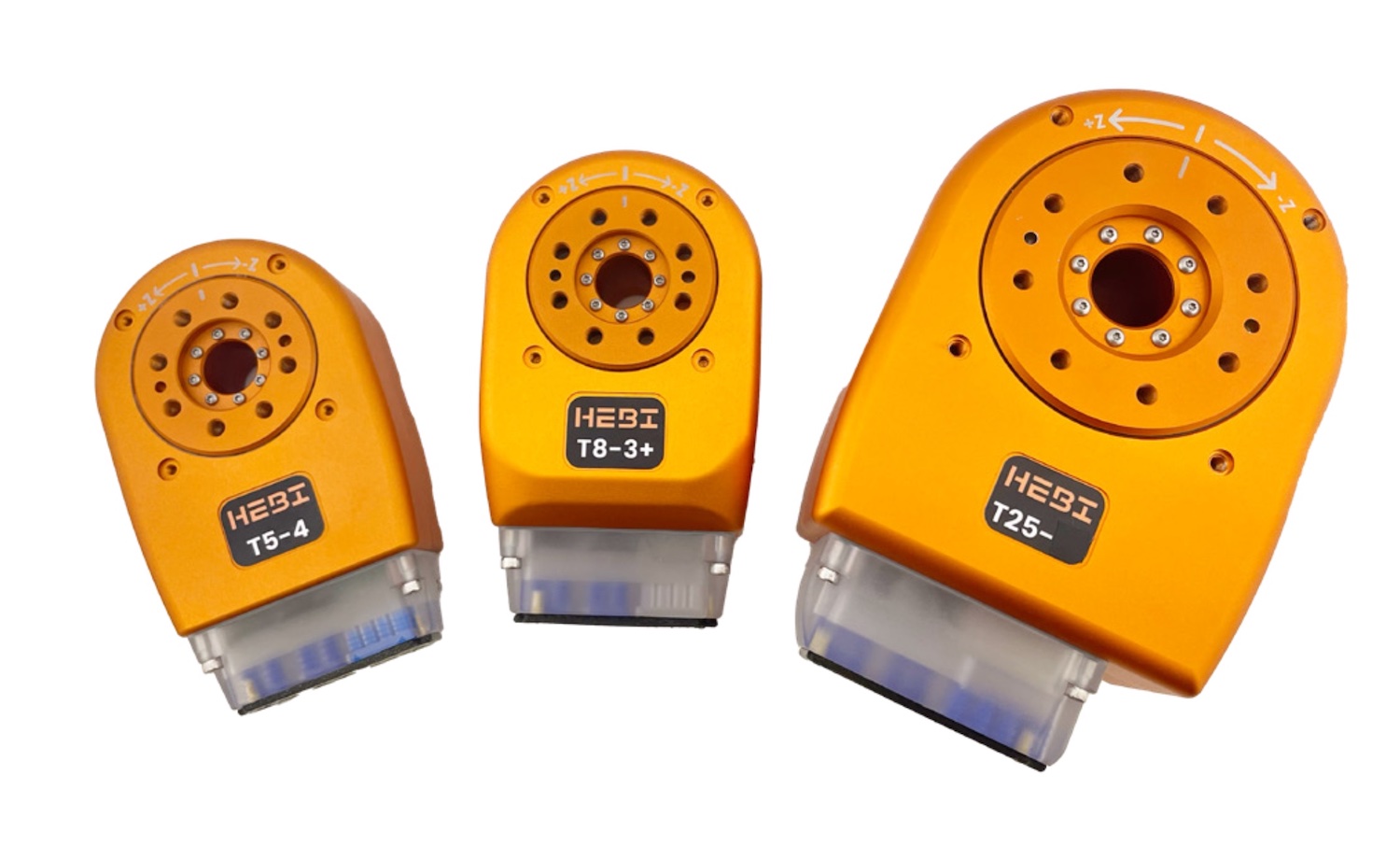
T-Series Actuator
|
The T-Series Actuators have replaced the X-Series Actuators in HEBI’s Catalog. The primary reasons for creating the T-Series were to: - Increase continuous torque, power, and operational lifetime - Make the actuators quicker, cleaner, and easier to integrate into a robotic system - Make the actuators more mechanically and electrically compatible with our R-Series Actuators All existing X-Series Actuators will continue to be supported. Software and API support will continue indefinitely. |
Getting Started
The following instructions are meant to get you up and running quickly if you are new to HEBI T-Series actuators. If you have any questions please:
-
Check the full online documentation at http://docs.hebi.us
-
Contact us at support@hebirobotics.com.
Connection Toolbox
This R/T-Series Connection Toolbox contains all of the necessary tools, wiring, and extra supplies to work with the T-Series or R-Series Actuators. A complete Bill of Materials can be found here: Connection Toolbox BOM
Download the Scope GUI
Go to docs.hebi.us and get the latest version of the Scope GUI for your computer (Windows, macOS, Linux).
Wiring Block Diagram

Here is a simple Block Diagram showing the wiring setup for the T-Series Actuator. All electronics shall be used with a 24-48V power supply. The communications runs off of 100 Mbps Ethernet converted in the Media Converter to Plastic Optical Fiber into the Actuator.
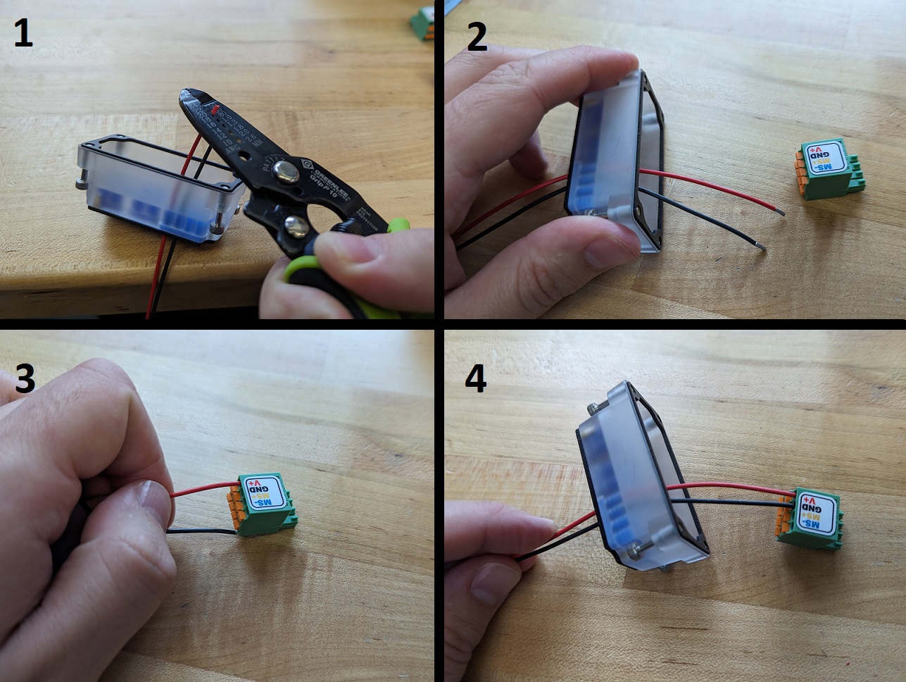
Feed Power Cables thru Wire Seals
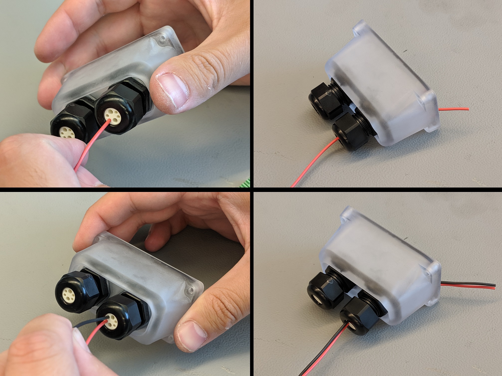
Take the Power cabling and feed the wires through the smaller holes on the connector cover. You can add a small amount of the Silicone Grease to the holes in the wire seal to help slide the cables through more easily. Additionally, you will want to line up the wire with the corresponding slot in the terminal block it will line up with.
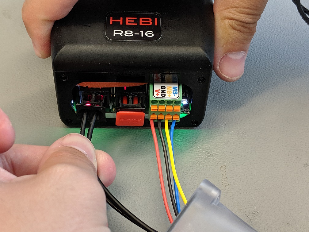
From left to right (left being the inside of the cover) the color/wiring order is:
-
V+ (Red)
-
GND (Black)
-
MS+ (Yellow)
-
MS- (Blue)
Connect Power Cables to Terminal Block
-
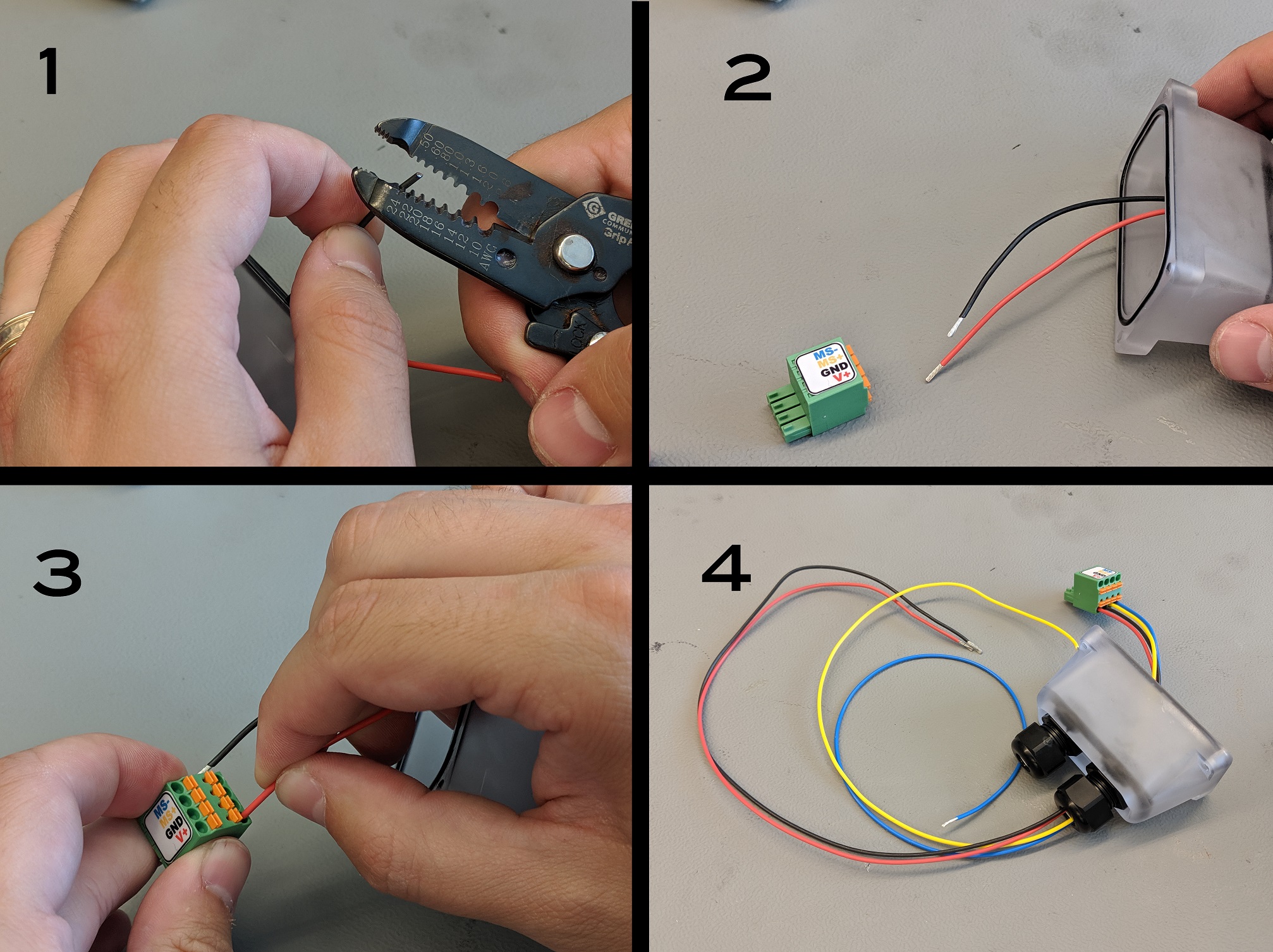
Strip the end of the power cables that are on the inside of the connector cover.
-
Grab a PP-2350-01 (Power/M-Stop Terminal Plug for R-Series Actuator).
-
Push the stripped cables into the corresponding slots on the Terminal Plug. To remove the cables from the Plug press in the orange tab that is above the corresponding slot and pull the cable.
-
Repeat these steps for all four of the Power (Red and Black) and M-Stop (Blue and Yellow) cables.
The M-Stop wires are not required to run the Actuators.
Connect Power
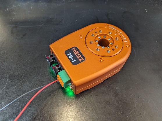
Plug in the power connection to the actuator.
| Do not hot-plug the actuators. Connecting and disconnecting the power while the power is on will cause sparking and may damage the actuator. Only connect and disconnect the power connector when power is off. |
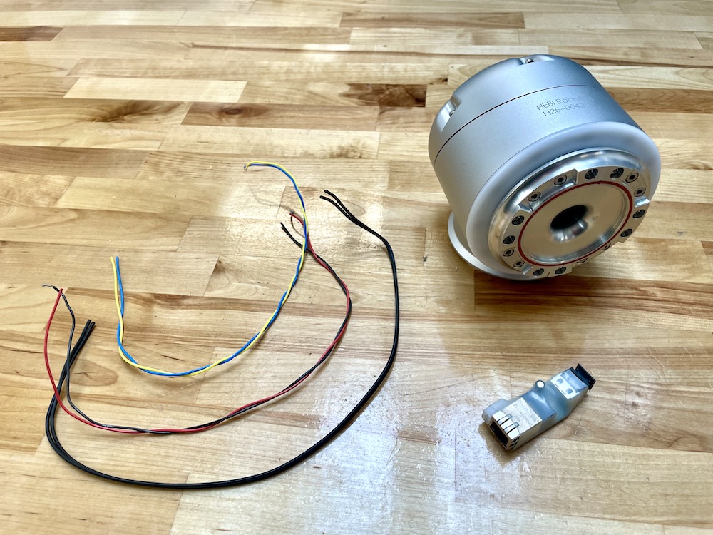
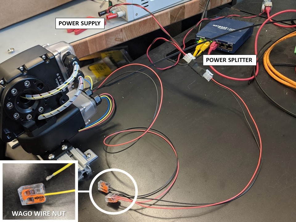
Power connection options to T-Series Actuators can vary and are dependant on the application. HEBI will provide WAGO Wire Nuts in order to initially connect flying lead connections to molex connector cables which can then be connected to HEBI power distribution boards. The image below is an example of wiring up a R-Series arm in a lab environment.
| Wiring for R-Series and T-Series Actuators is identical with the only difference being the polycarbonate cover that protects the connectors for the Actuators. |
Trimming and Splitting Duplex Fiber Cables
The Plastic Optical Fiber (POF) comes in single strand and duplex paired strands. Use the PP-2402-01 (POF Termination Cutter) provided in the Toolbox to cut the cables and also to split the duplex pair in order to pass thru the wire seals in the connector cover and install in the fiber connectors.
Connect Media Converter
-
Take the A-2256-01 (Fiber-Ethernet Media Converter) and connect a power cable with a Molex Minifit Jr connector.
-
Use an Ethernet cable to connect the Media Converter to a router or switch on your local area network (LAN).
-
Pull the outer piece of the Fiber Connector outwards and install the end of the Fiber cables into the connector.
-
Push the outer piece of the Fiber Connector inwards as to hold the Fiber cable in place.
Feed Fiber Cables thru Wire Seal
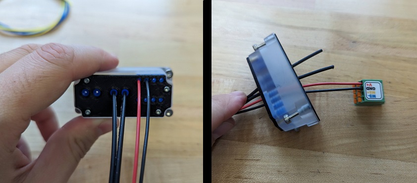
Take the other end of the Plastic Optical Fiber (POF) cabling and feed it through one of the pair of larger holes on the connector cover. You can add a small amount of the Silicone Grease to the holes in the wire seal to help slide the cables through more easily.
Turn On Power
Connect the other ends of the power cables to a power source. Turn on the power supply, or connect/activate batteries. The actuators run on any DC voltage source between 24V-48V.
| A T-Series Actuator can draw up to 50W-150W at peak power, but draws less than 2W at idle. Typical continuous power draw for most applications is much lower than the peak power draw, usually 10W-20W. It is important to choose an appropriate power supply for your application. See the Power section of the online documentation for more information. |
The Status LED will start blinking green/orange while the actuator is trying to obtain an IP address. One of the fiber cables will have a bright red light coming thru it.
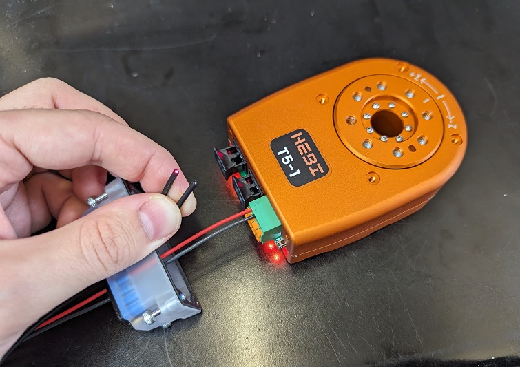
Connect Fiber Ethernet
The Fiber Connectors on the Actuator should have a red light coming out from one of the two receptacles. Take the Fiber Cable and connect it to one of the Fiber connectors on the Actuator.
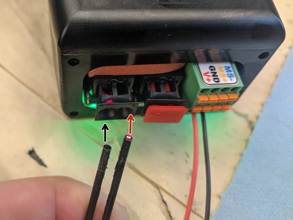
| The Cable with the red light shining thru it should go into the port that has no light coming from it and vice-versa. |
Actuators ship by default configured to run on DHCP. This means that to work correctly there needs to be a router on the network configured for DHCP. There are methods for setting a Static IP address if no router is available.
| It is important to use a wired ethernet connection between your computer and actuators for maximum reliability. A wireless connection will work, and is generally still useful for viewing feedback in the Scope GUI. However, there will be some amount of packet loss and increased latency that may cause issues with motor control. |
Restart Power
Turn off and turn back on actuator power. Again, the Status LED will start blinking green/orange while the actuator is trying to obtain an IP address. After a few seconds, the LED will change to a slow green fade. Once the actuator is in this state it will respond to commands and provide feedback from its internal sensors.
| If the actuator does not get an IP address, make sure that your network has a router configured for DHCP. Some corporate and institutional networks may also have network security features set up that can interfere with DHCP and/or UDP broadcast, which can create cases where actuators are assigned IP addresses but will not be visible in Scope or the APIs. If you suspect this is the case please talk with your network administrator. |
Wiring up Multiple Actuators
When connecting multiple actuators:
-
Both the fiber and power connections can be daisy-chained thru the actuators. It does not matter which ports are used to daisy-chain.
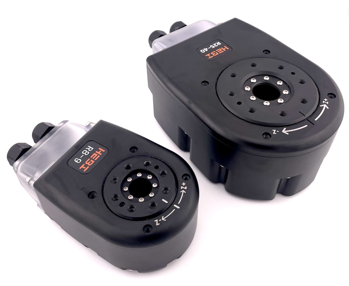
R-Series Actuator
| The R-Series Actuators are electrically compatible with our T-Series Actuators so this guide will look similar to the T-Series Actuator Quickstart Guide. |
Getting Started
The following instructions are meant to get you up and running quickly if you are new to HEBI R-Series actuators. If you have any questions please:
-
Check the full online documentation at http://docs.hebi.us
-
Contact us at support@hebirobotics.com.
Connection Toolbox
This R/T-Series Connection Toolbox contains all of the necessary tools, wiring, and extra supplies to work with the T-Series or R-Series Actuators. A complete Bill of Materials can be found here: Connection Toolbox BOM
Download the Scope GUI
Go to docs.hebi.us and get the latest version of the Scope GUI for your computer (Windows, macOS, Linux).
Wiring Block Diagram
Here is a simple Block Diagram showing the wiring setup for the R-Series Actuator. All electronics shall be used with a 24-48V power supply. The communications runs off of 100 Mbps Ethernet converted in the Media Converter to Plastic Optical Fiber into the Actuator.
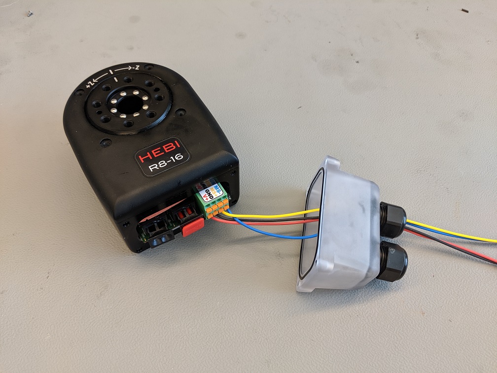
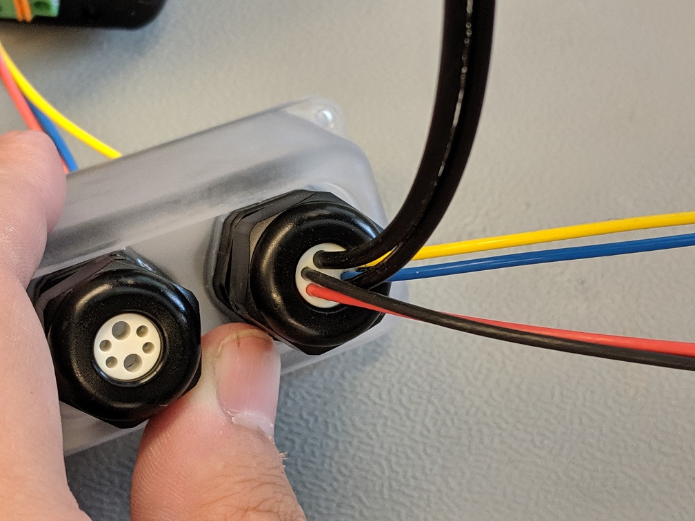
Feed Power Cables thru Cord Grip
Take the Power cabling and feed the wires through the smaller holes on one of the cord grips. You can add a small amount of the Silicone Grease to the holes in the Cord Grip to help slide the cables through more easily.
Connect Power Cables to Terminal Block
-
Strip the end of the power cables that are on the inside of the connector cover.
-
Grab a PP-2350-01 (Power/M-Stop Terminal Plug for R-Series Actuator).
-
Push the stripped cables into the corresponding slots on the Terminal Plug. To remove the cables from the Plug press in the orange tab that is above the corresponding slot and pull the cable.
-
Repeat these steps for all four of the Power (Red and Black) and M-Stop (Blue and Yellow) cables.
Connect Power
Plug in the power connection to the actuator.
| Do not hot-plug the actuators. Connecting and disconnecting the power while the power is on will cause sparking and may damage the actuator. Only connect and disconnect the power connector when power is off. |
Power connection options to R-Series Actuators can vary and are dependant on the application. HEBI will provide WAGO Wire Nuts in order to initially connect flying lead connections to molex connector cables which can then be connected to HEBI power distribution boards. The image below is an example of wiring up a R-Series arm in a lab environment.
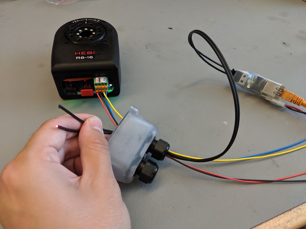
Trimming and Splitting Duplex Fiber Cables
The Plastic Optical Fiber (POF) comes in single strand and duplex paired strands. Use the PP-2402-01 (POF Termination Cutter) provided in the Toolbox to cut the cables and also to split the duplex pair in order to pass thru the sealing Cord Grips and install in the fiber connectors.
Connect Media Converter
-
Take the A-2256-01 (Fiber-Ethernet Media Converter) and connect a power cable with a Molex Minifit Jr connector.
-
Use an Ethernet cable to connect the Media Converter to a router or switch on your local area network (LAN).
-
Pull the outer piece of the Fiber Connector outwards and install the end of the Fiber cables into the connector.
-
Push the outer piece of the Fiber Connector inwards as to hold the Fiber cable in place.
Feed Fiber Cables thru Cord Grip
Take the other end of the Plastic Optical Fiber (POF) cabling and feed it through the two larger holes on the cord grip that has the power cables. You can add a small amount of the Silicone Grease to the holes in the Cord Grip to help slide the cables through more easily.
Turn On Power
Connect the other ends of the power cables to a power source. Turn on the power supply, or connect/activate batteries. The actuators run on any DC voltage source between 24V-48V.
| A R-Series Actuator can draw up to 50W-150W at peak power, but draws less than 2W at idle. Typical continuous power draw for most applications is much lower than the peak power draw, usually 10W-20W. It is important to choose an appropriate power supply for your application. See the Power section of the online documentation for more information. |
The Status LED will start blinking green/orange while the actuator is trying to obtain an IP address. One of the fiber cables will have a bright red light coming thru it.
Connect Fiber Ethernet
The Fiber Connectors on the Actuator should have a red light coming out from one of the two receptacles. Take the Fiber Cable and connect it to one of the Fiber connectors on the Actuator.
| The Cable with the red light shining thru it should go into the port that has no light coming from it and vice-versa. |
Actuators ship by default configured to run on DHCP. This means that to work correctly there needs to be a router on the network configured for DHCP. There are methods for setting a Static IP address if no router is available.
| It is important to use a wired ethernet connection between your computer and actuators for maximum reliability. A wireless connection will work, and is generally still useful for viewing feedback in the Scope GUI. However, there will be some amount of packet loss and increased latency that may cause issues with motor control. |
Restart Power
Turn off and turn back on actuator power. Again, the Status LED will start blinking green/orange while the actuator is trying to obtain an IP address. After a few seconds, the LED will change to a slow green fade. Once the actuator is in this state it will respond to commands and provide feedback from its internal sensors.
| If the actuator does not get an IP address, make sure that your network has a router configured for DHCP. Some corporate and institutional networks may also have network security features set up that can interfere with DHCP and/or UDP broadcast, which can create cases where actuators are assigned IP addresses but will not be visible in Scope or the APIs. If you suspect this is the case please talk with your network administrator. |
Wiring up Multiple Actuators
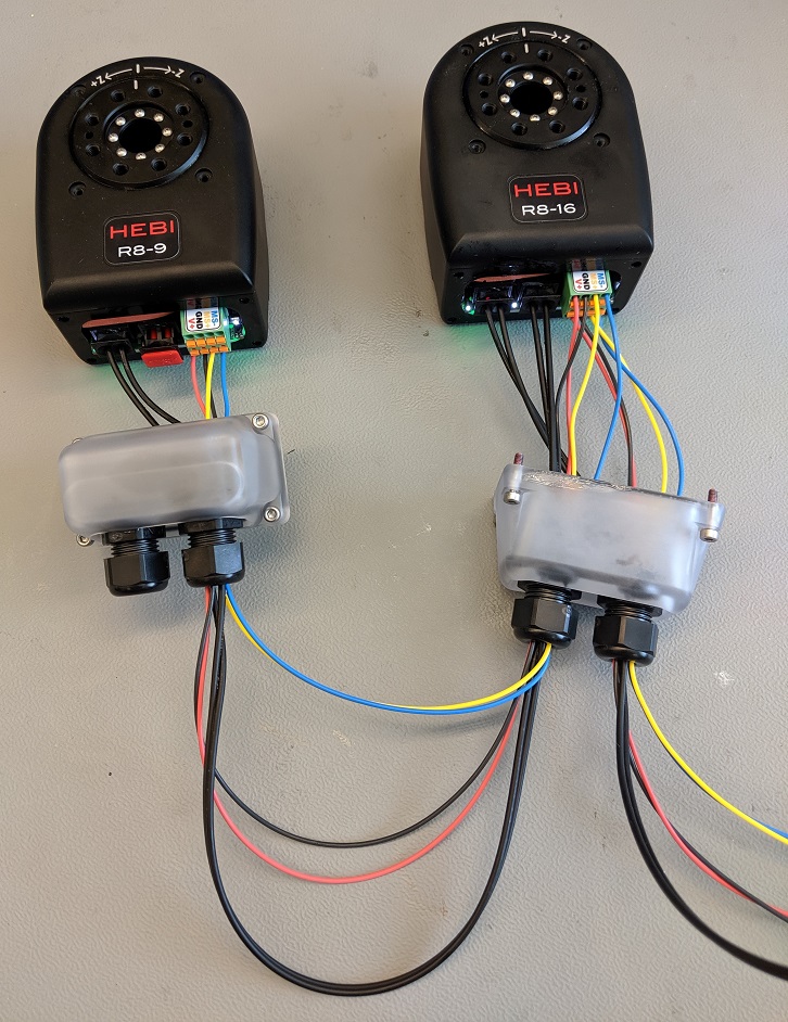
When connecting multiple actuators:
-
Both the fiber and power connections can be daisy-chained thru the actuators. It does not matter which ports are used to daisy-chain.
-
It is best to group the six cables for Power, M-Stop, and Fiber in the same cord grip to make re-configuring and re-routing wires more organized.
X-Series Actuator
|
The X-Series Actuators have been Discontinued. The information below is for documentation and support purposes. Please contact support@hebirobotics.com with any questions. |
Getting Started
The following instructions are meant to get you up and running quickly if you are new to HEBI X-Series actuators. If you have any questions please:
-
Check the full online documentation at http://docs.hebi.us
-
Contact us at support@hebirobotics.com.
Download the Scope GUI
Go to docs.hebi.us and get the latest version of the Scope GUI for your computer (Windows, macOS, Linux).
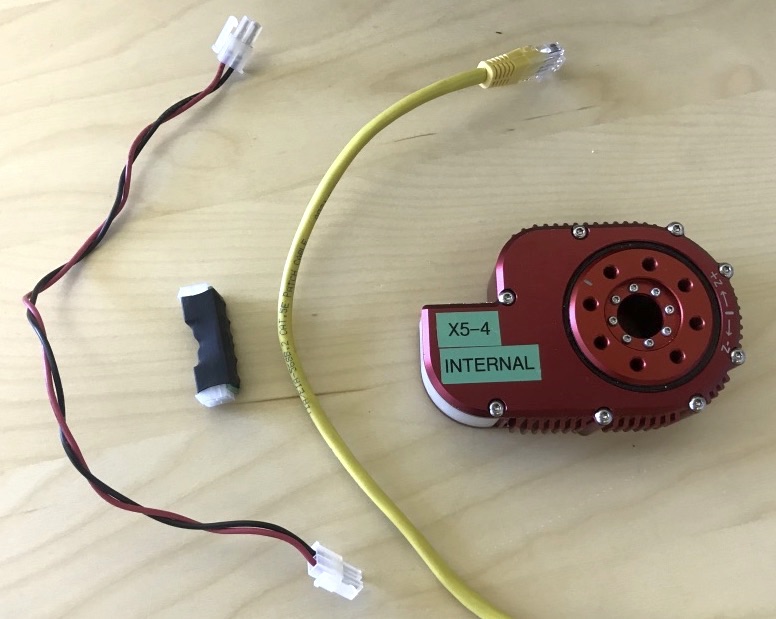
Connect Ethernet
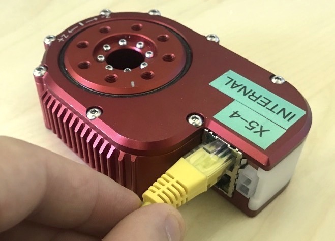
Connect a standard ethernet cable to either one of the RJ45 ports on the module. Connect the other end of the cable to a router or switch on your local area network (LAN).
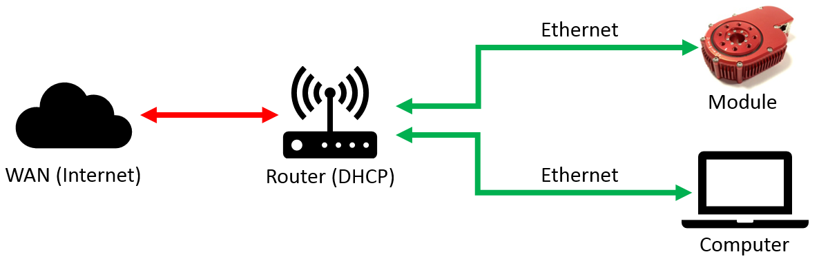
Actuators ship by default configured to run on DHCP. This means that to work correctly there needs to be a router on the network configured for DHCP. There are methods for setting a Static IP address if no router is available.
| It is important to use a wired ethernet connection between your computer and modules for maximum reliability. A wireless connection will work, and is generally still useful for viewing feedback in the Scope GUI. However, there will be some amount of packet loss and increased latency that may cause issues with motor control. |
Connect Power
Using the provided cabling, or any other compatible Molex Mini-Fit Jr. connectors, plug in the power connection to the module.
| Do not hot-plug the modules. Connecting and disconnecting the power while the power is on will cause sparking and may damage the module. Only connect and disconnect the power connector when power is off. |
Turn On Power
Turn on the power supply, or connect/activate batteries. The modules run on any DC voltage source between 24V-48V.
| An X-Series actuator module can draw up to 50W-150W at peak power, but draws less than 2W at idle. Typical continuous power draw for most applications is much lower than the peak power draw, usually 10W-20W. It is important to choose an appropriate power supply for your application. See the Power section of the online documentation for more information. |
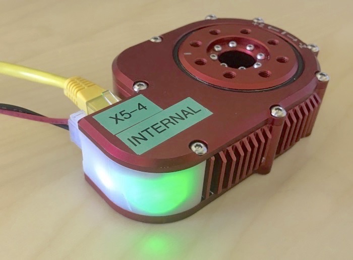
The Status LED will start blinking green/orange while the actuator is obtaining an IP address. After a few seconds, the LED will change to a slow green fade. Once the module is in this state it will respond to commands and provide feedback from its internal sensors.
| If the actuator does not get an IP address, make sure that your network has a router configured for DHCP. Some corporate and institutional networks may also have network security features set up that can interfere with DHCP and/or UDP broadcast, which can create cases where modules are assigned IP addresses but will not be visible in Scope or the APIs. If you suspect this is the case please talk with your network administrator. |
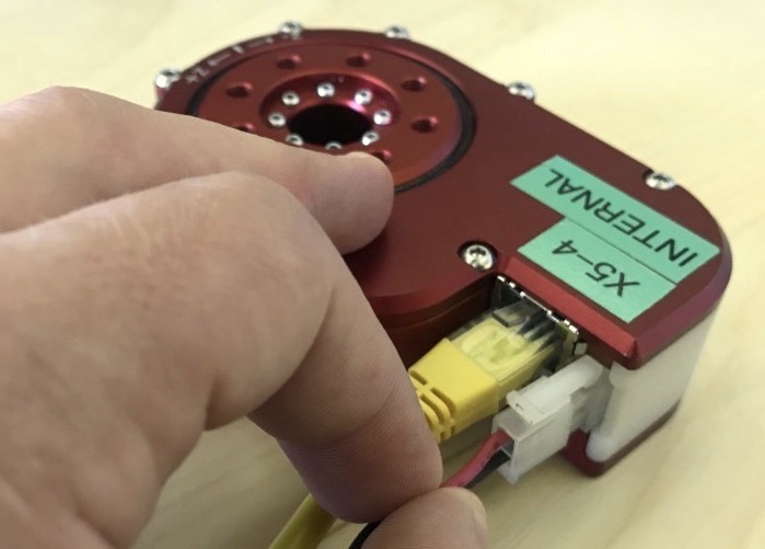
Wiring up Multiple Modules
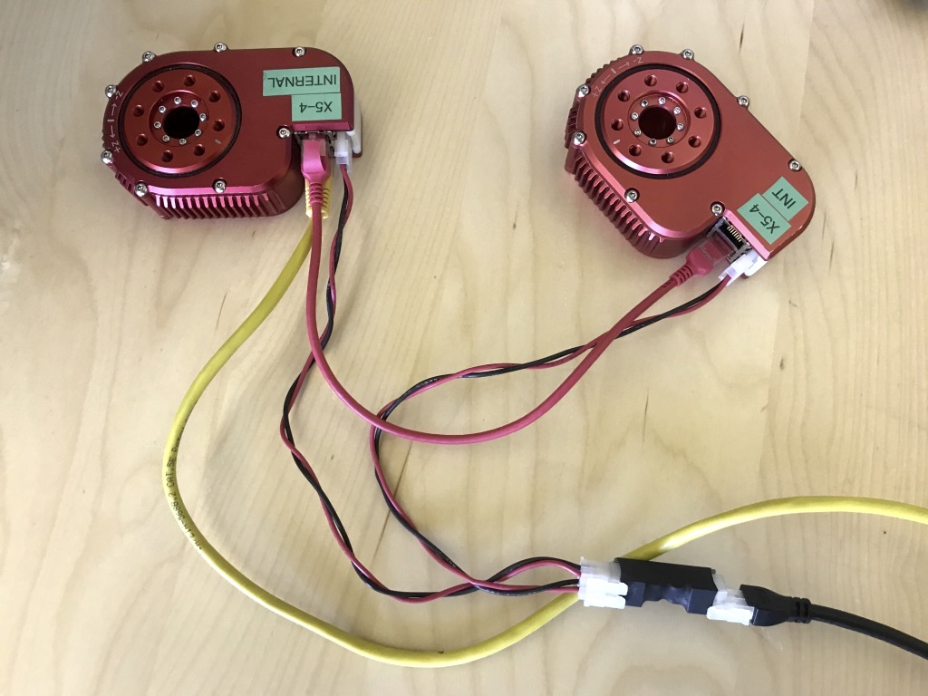
The X-Series actuators are designed to be quickly wired and chained together to make assembling full robotic systems as easy as possible. When connecting multiple modules:
-
The ethernet connection can be daisy-chained thru the modules. It does not matter which ports are used to daisy-chain.
-
The power connection needs to be split external to the module, using the provided power splitters or using other custom wiring.
Mechanically Mounting Modules
The X-Series actuators have threaded holes for M5 metric screws on their top and bottom sides for mounting. If you are using standard HEBI connection parts, the appropriate hardware is provided.
| Be careful to use the appropriate length screws when mounting the actuators. Using screws that are too long may damage the actuator if they are tightened while bottomed out in the threaded holes. |
CR1 Camera Module
Getting Started
The following instructions are meant to get you up and running quickly with the HEBI CR1 Camera Module. If you have any questions please:
-
Check the full online documentation at http://docs.hebi.us
-
Contact us at support@hebirobotics.com.
Download the Scope GUI and HEBI-Video
Go to docs.hebi.us and get the latest version of the Scope GUI and Video Acquisition tools for your computer (Windows, macOS, Linux).
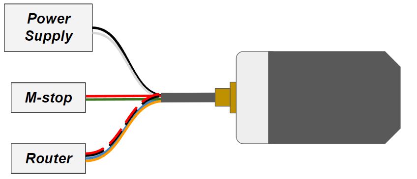
RJ45 Configuration
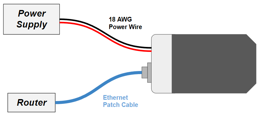
Here is a simple Block Diagram showing the wiring setup for the RJ45 configuration of the CR1 module. All electronics shall be used with a 24-48V power supply. The communications runs off of 100 Mbps Ethernet.
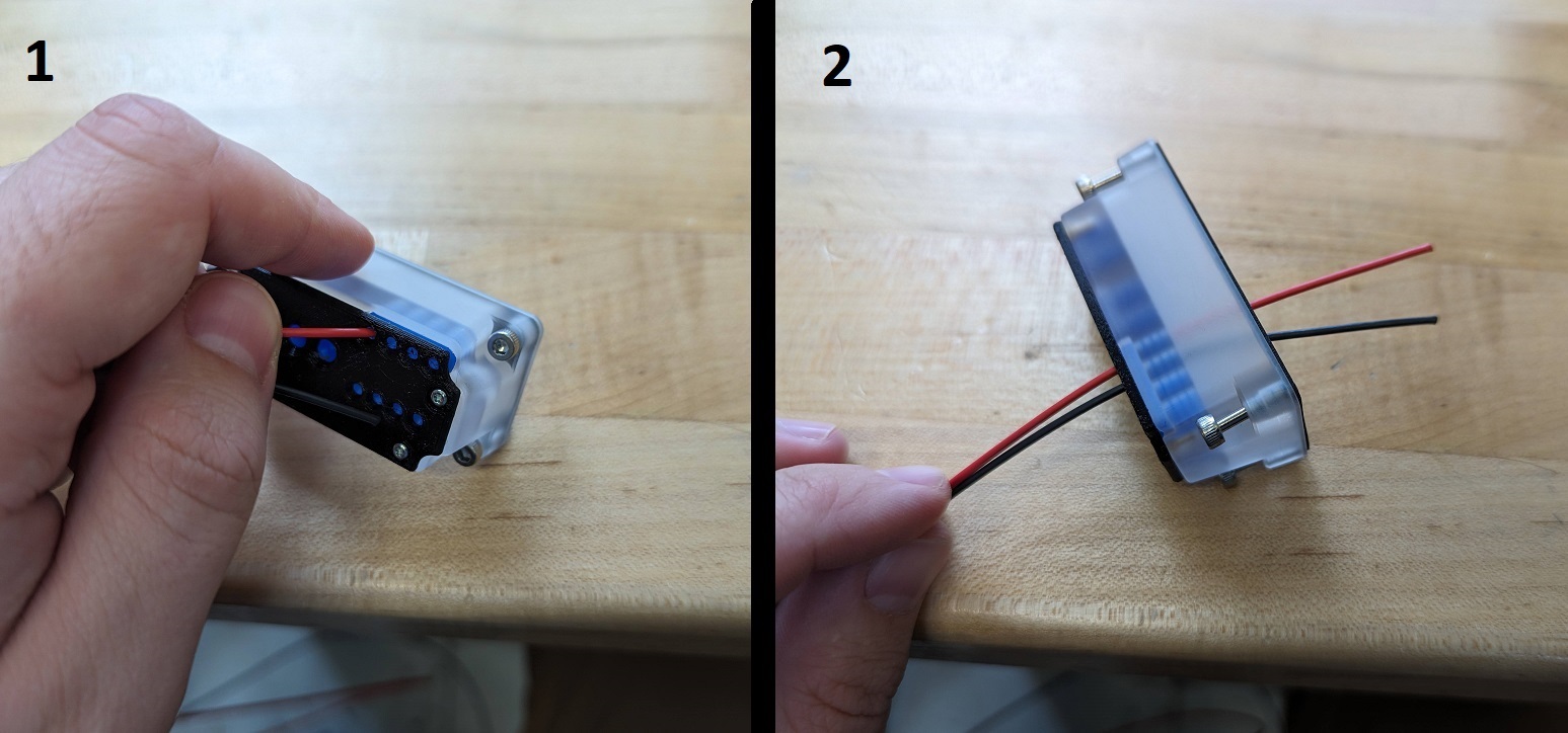
Installing/Changing Power Wires
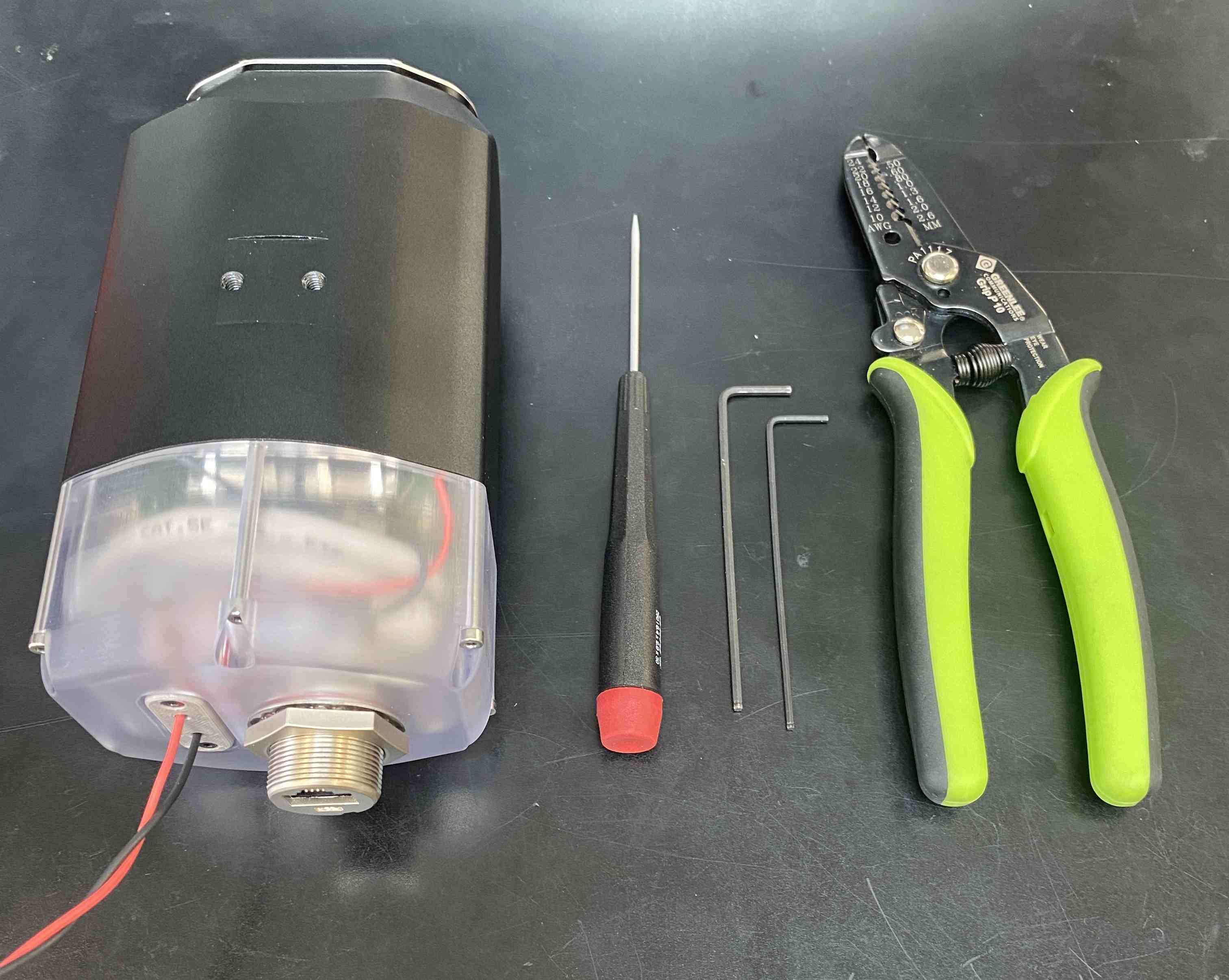
To install or swap the power wires on the module, you will need 1.5mm and 2mm hex wrenches, a small flathead screwdriver, and wire strippers.
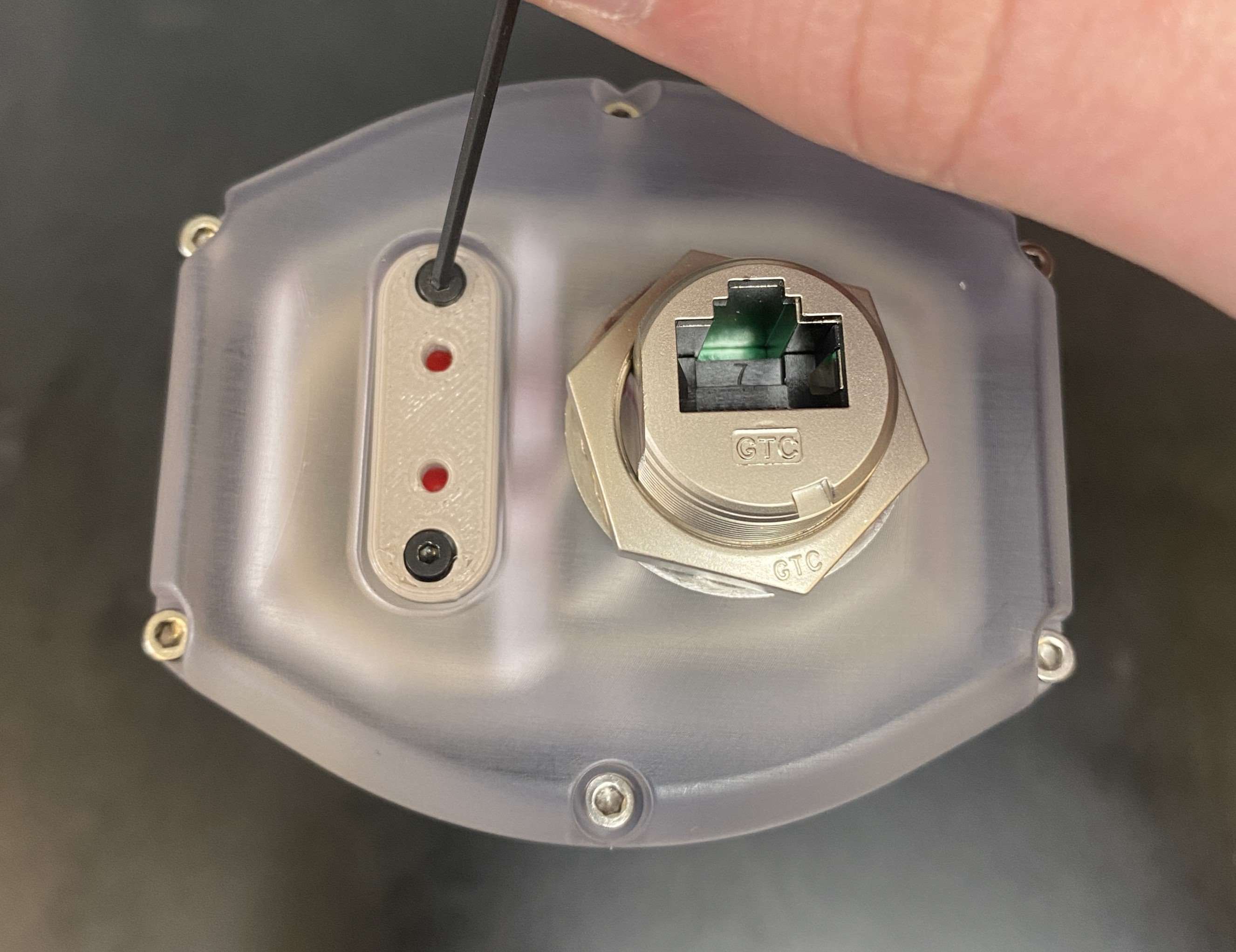
|
Remove the wire seal retainer using the 1.5mm hex wrench |
|
Remove the six screws holding the cap with the 2mm hex wrench |
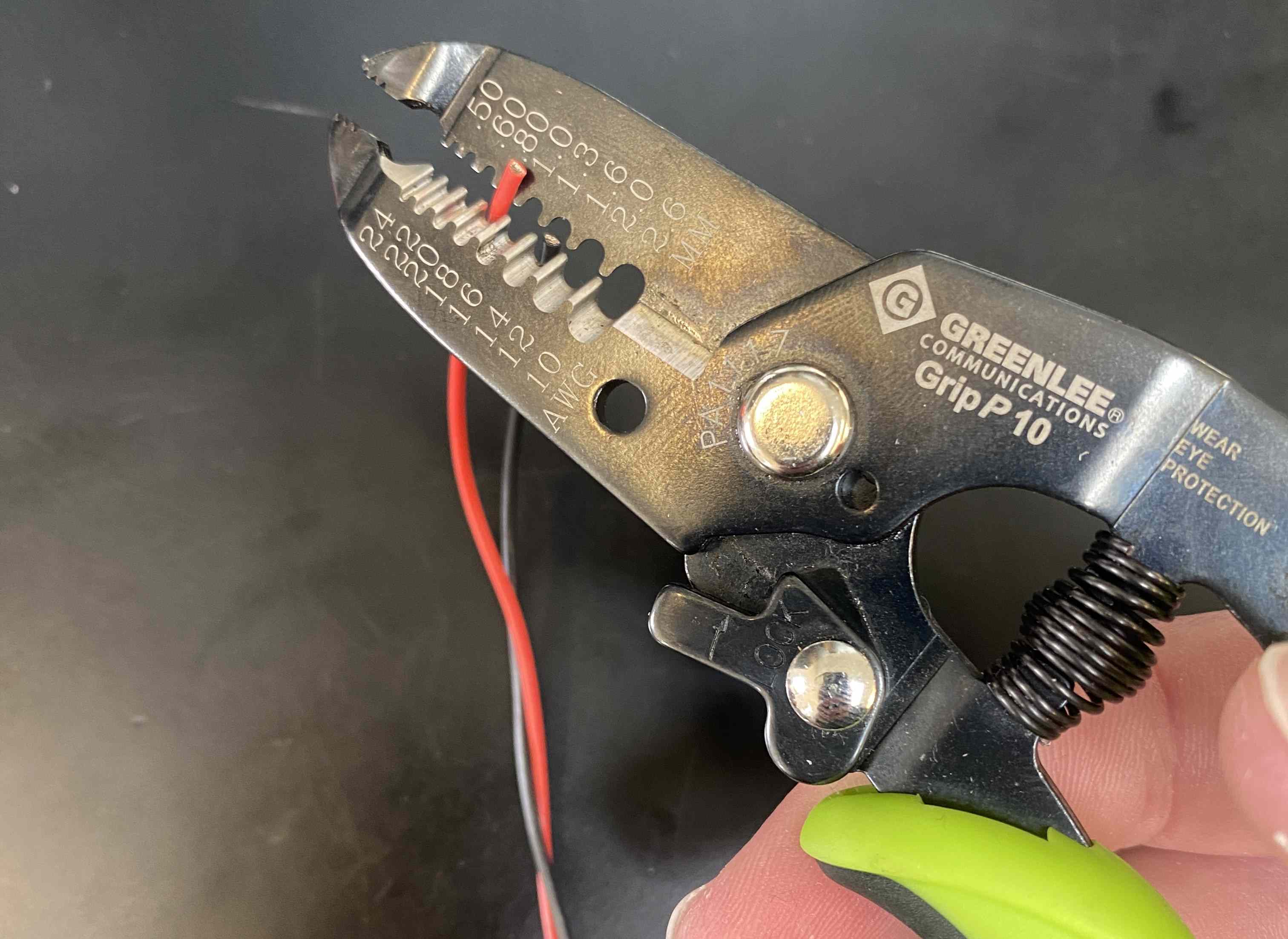
|
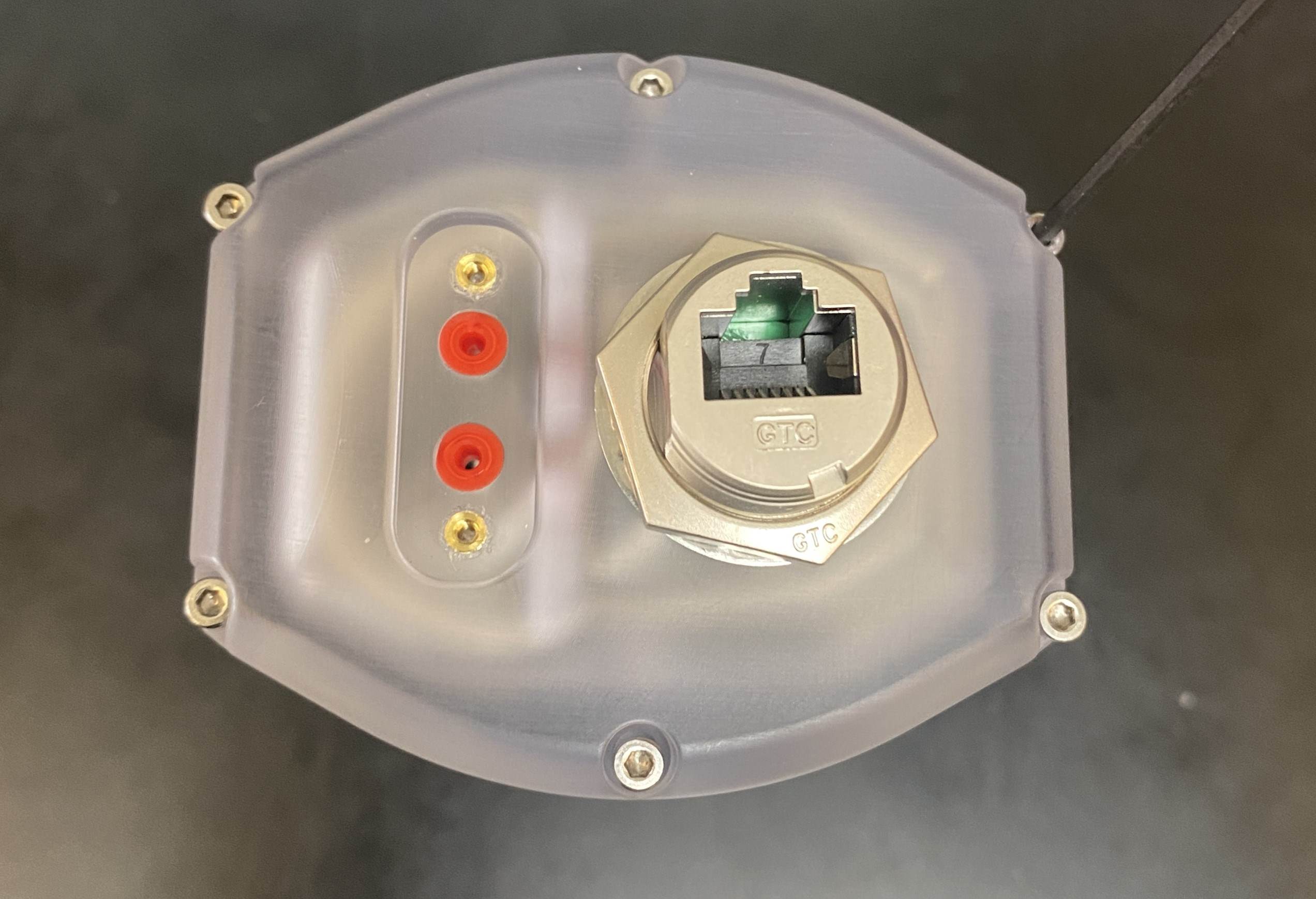
Strip the red and black 18AWG wire about 4mm |
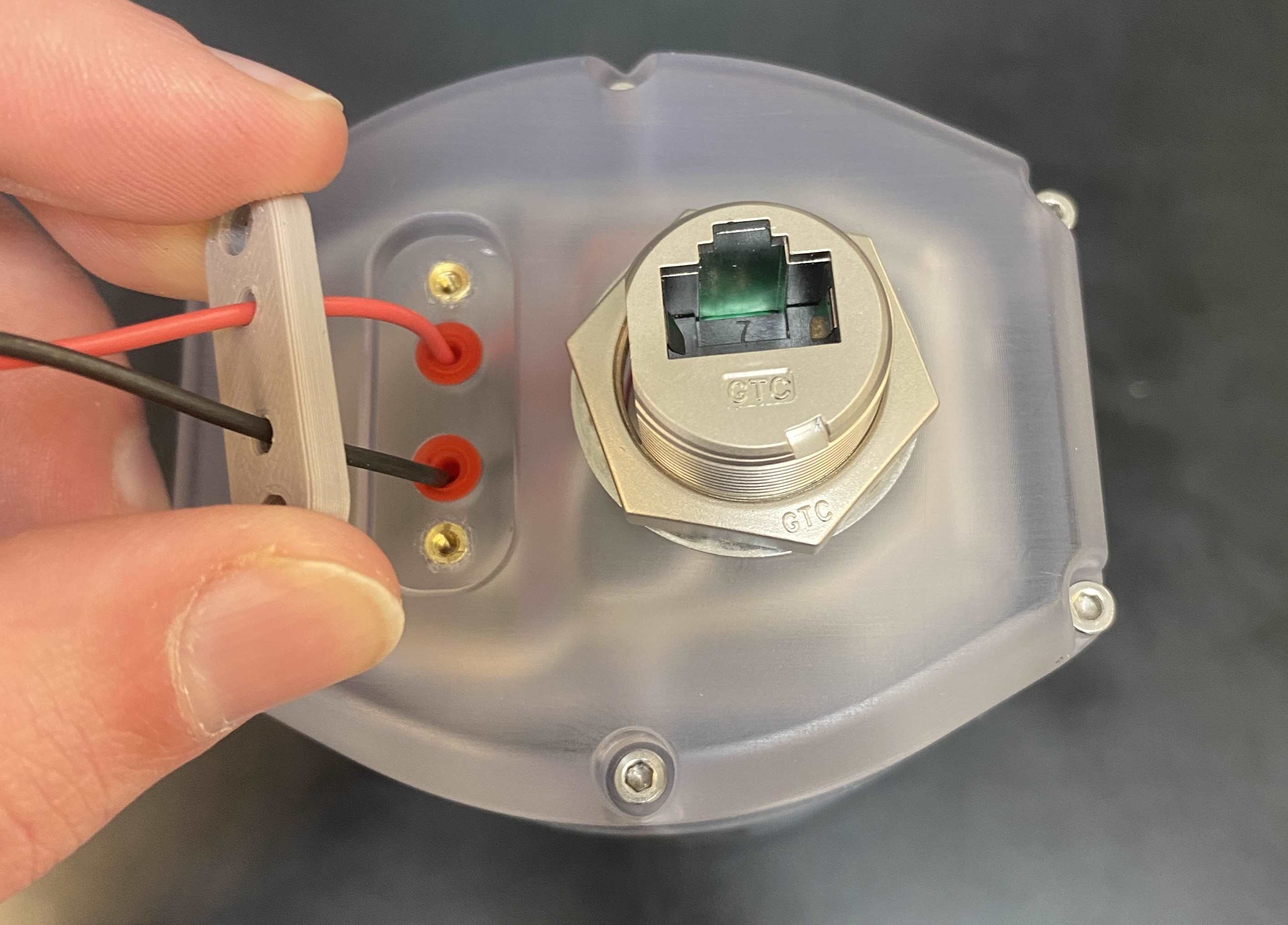
|
Run the stripped wire through the wire seal retainers and then through the wire seals on the cap |
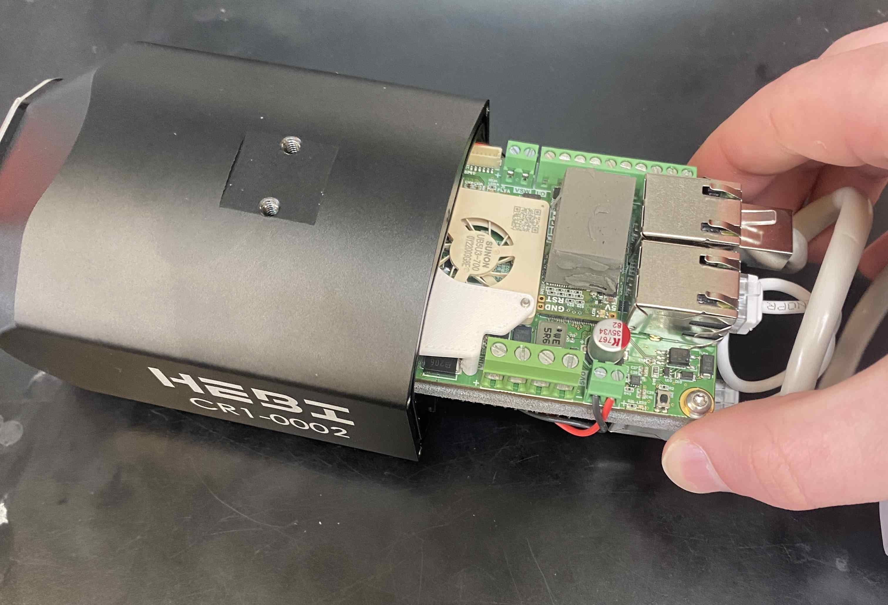
|
Slide out the circuit boards until you reveal the large power terminal on the left side of the module |
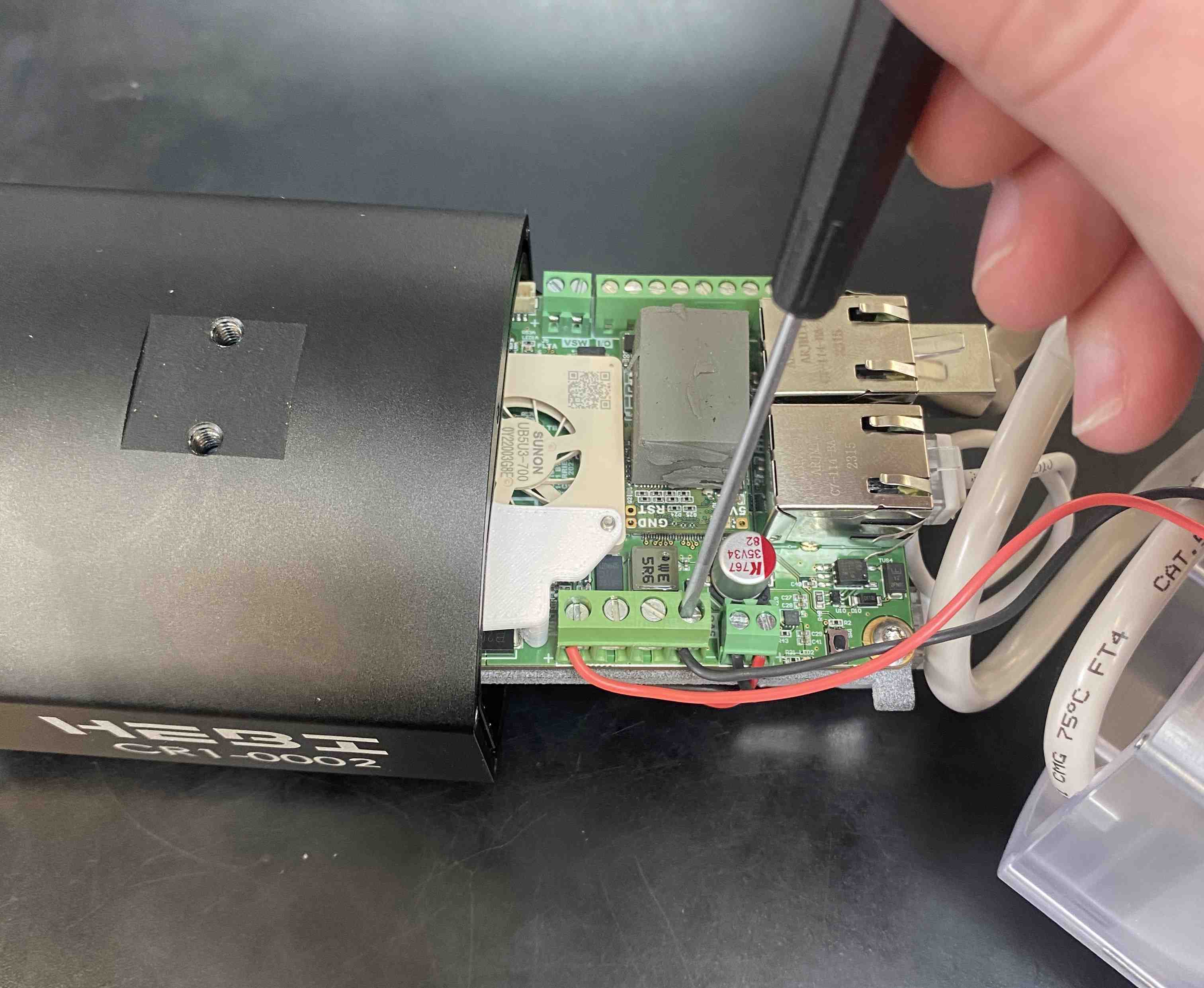
|
Insert the wires into the screw terminals as shown and tighten them using the flathead screwdriver |
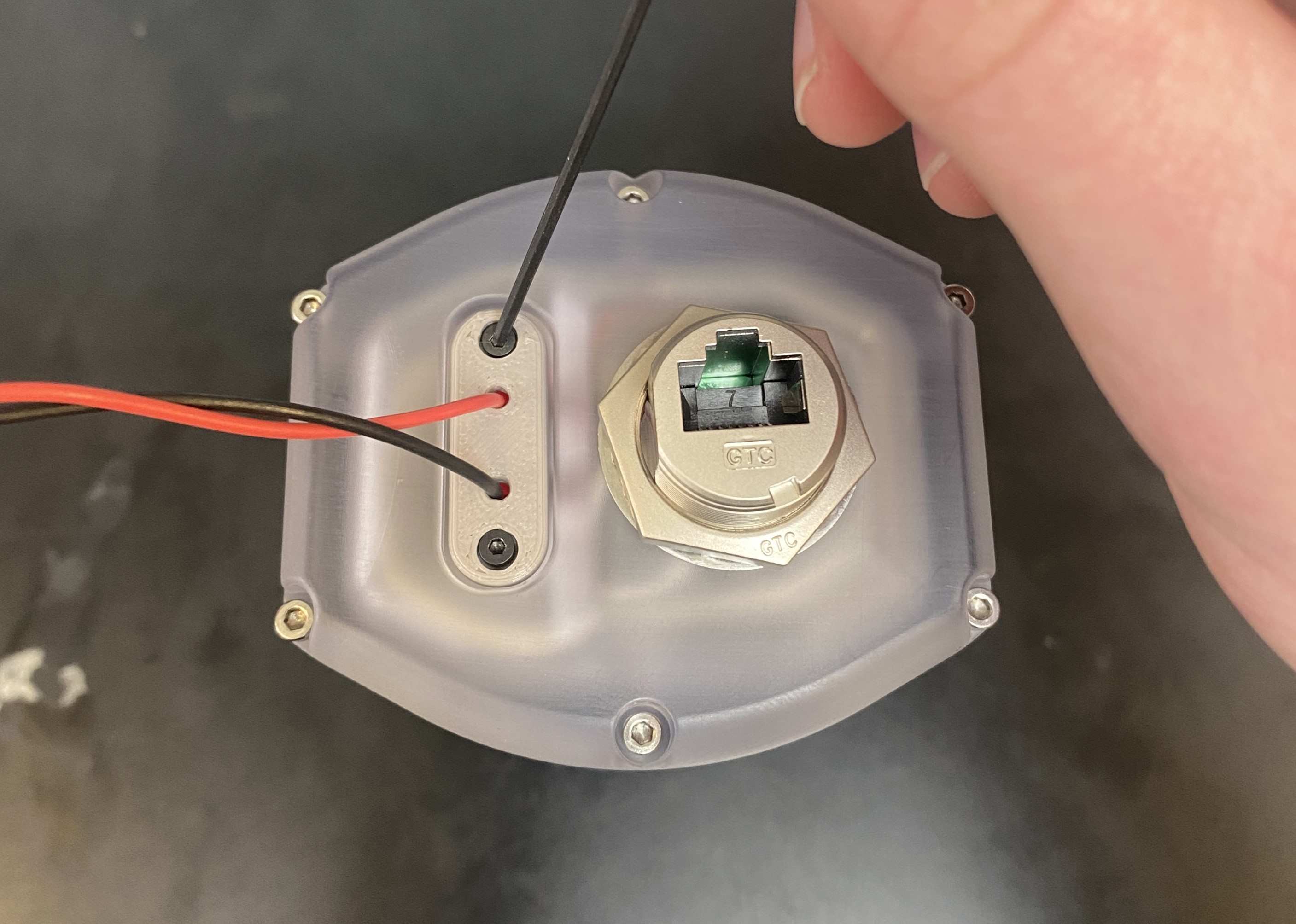
|
Re-assemble the cap and make sure to tighten down the wire seal retainer |
Connect Data
To maintain the module’s IP67 rating, use a Waterproof Cable or a Waterproof Connector. For use in controlled environments, you can use a standard Ethernet patch cable.
Subconn Configuration
The Subconn connector configuration allows the module to be used during prolonged submersion. Due to the sealed nature of this confguration, it is not recommended to open the module unnecesarily. Power and data are both transmitted using the MCBH8F Micro-Circular Subconn connector which interfaces with a MCIL8M Subconn connector.
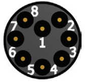
Subconn Wiring
Should you need to replace your Subconn cable, the pinout is provided below.
Subconn Pin |
Wire Color |
Function |
1 |
Black |
Power |
2 |
White |
Ground |
3 |
Red |
Mstop+ |
4 |
Green |
Mstop- |
5 |
Orange |
ETH+ (RJ45 pin 1) |
6 |
Blue |
Eth- (RJ45 pin 2) |
7 |
White/Black |
Eth+ (RJ45 pin 3) |
8 |
Red/Black |
Eth- (RJ45 pin 6) |
Viewing the Camera Stream
To view the camera stream, follow the HEBI-video instructions found here.
Controlling the LEDs
The CR1 Module uses a HEBI I/O Utility Board to control the floodlight LEDs on either side of the camera lense. To set the brightness of the LEDs, set a value of 0.1-0.5 for I/O channel f3. Turn the lights on and off by setting I/O channel e5 to true/false. This can be done through scope or programmatically.
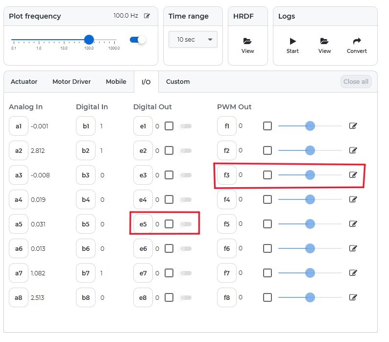
Example commands for the MATLAB API shown below.
# Setup I/O group and command structure
ioGroup = HebiLookup.newGroupFromNames( CR1-0001, {'CR1-0001_IO'} );
ledCmd = IoCommandStruct();

# Set PWM value
ledCmd('f3') = 0.25;

# Update LED on/off
ledCmd('e5') = true;

# Send command to I/O board
ioGroup.send(ledCmd);
Scope
Open the Scope GUI
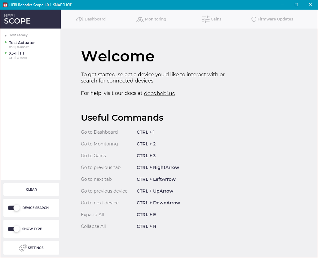
When Scope opens, it will show the Welcome Tab, which provides an overview of useful key-combinations for navigating the interface.
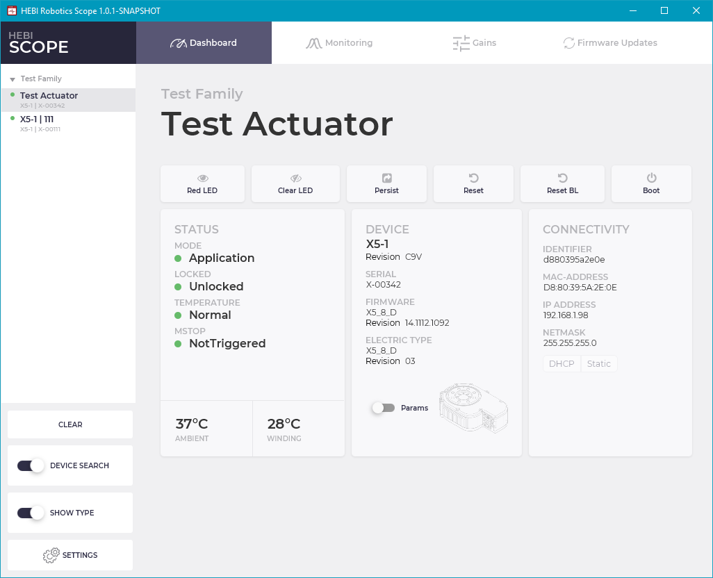
You can then select a device on the list from the left side and display its information in the Dashboard Tab.
Play Around
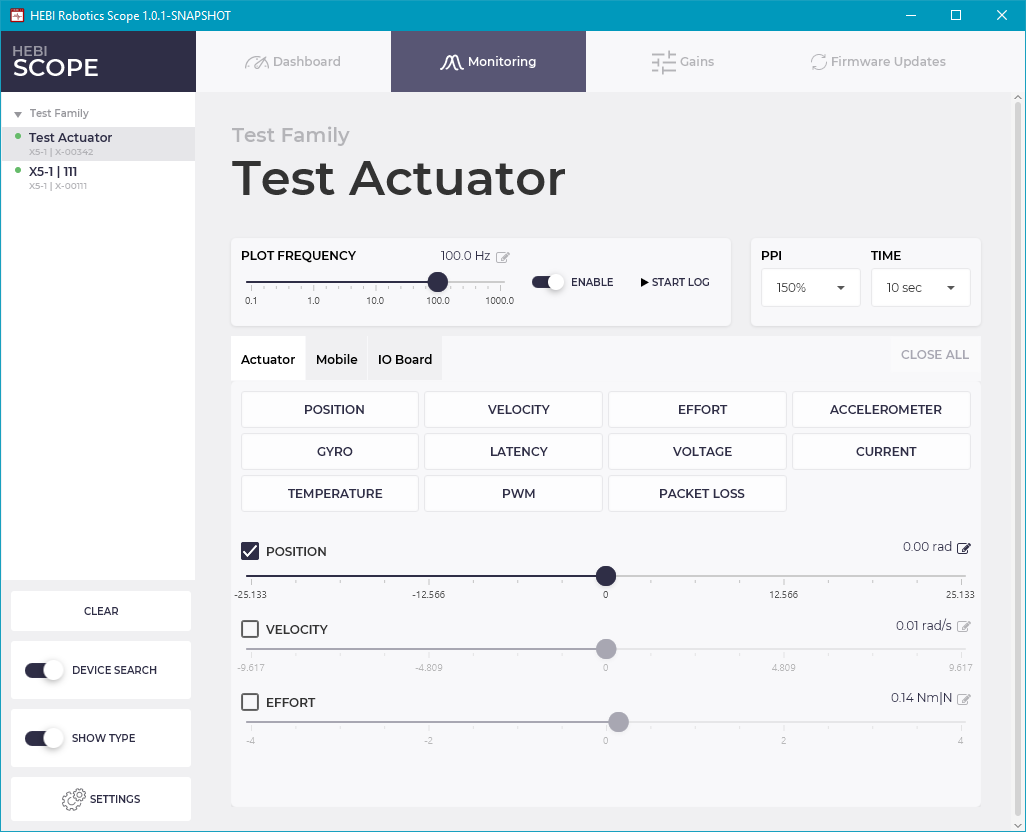
Feel free to play with the module to get a feel for its capabilities. In the lower section of the Monitoring Tab in Scope there are sliders for controlling position, velocity, and effort. There are also buttons in the upper section of the Monitoring Tab for plotting feedback from the various sensors in the module.
Sending Commands
Commands section of the Monitoring Tab has sliders for commanding different aspects of an actuator’s motion.
The details of how an actuator will respond to commands will depend on the Control Strategy and the gains on the actuator. Out of the box, an actuator will start up in Control Strategy 3, with gains that perform well under light loads. For heavier loads or multi-DOF systems the actuator gains will likely have to be tuned for the specific application. Actuator control and tuning is a complex topic and it is detailed more completely in the online documentation in the Motor Control section.
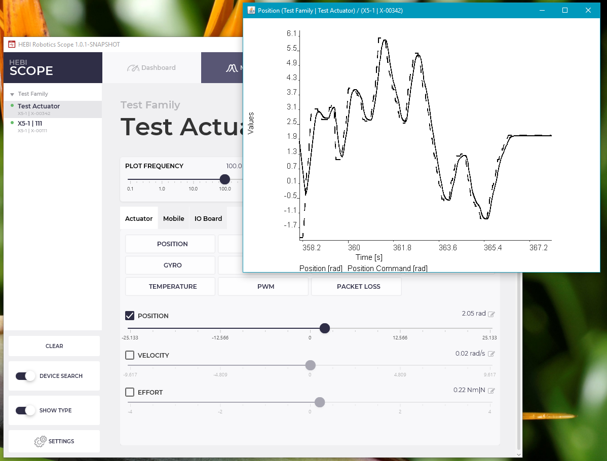
You can view the both commanded and feedback position, velocity, and effort by clicking the corresponding button in the upper portion of the Monitoring Tab.
Position Control
The top slider in the Commands section controls the output position of the actuator in radians. Dragging the slider will send new position commands.
Velocity Control
The middle slider in the Commands section controls the output velocity of the actuator in radians / second. Dragging the slider will send new velocity commands, causing the actuator output to turn continuously.
Effort (Torque) Control
The bottom slider in the Commands section controls the output effort of the actuator. For the R-Series Actuators this is the output torque in Newton-meters. Dragging the slider will send new effort commands.
| Torque control can be a somewhat unintuitive at first. A commanded torque in one direction can cause the output of an actuator to spin up to its maximum speed until sees a load that allows it to exert the commanded torque. |
Viewing Feedback
Position / Velocity / Effort (Torque)
You can view the both commanded and feedback position, velocity, and effort by clicking the corresponding button in the upper portion of the Monitoring Tab.
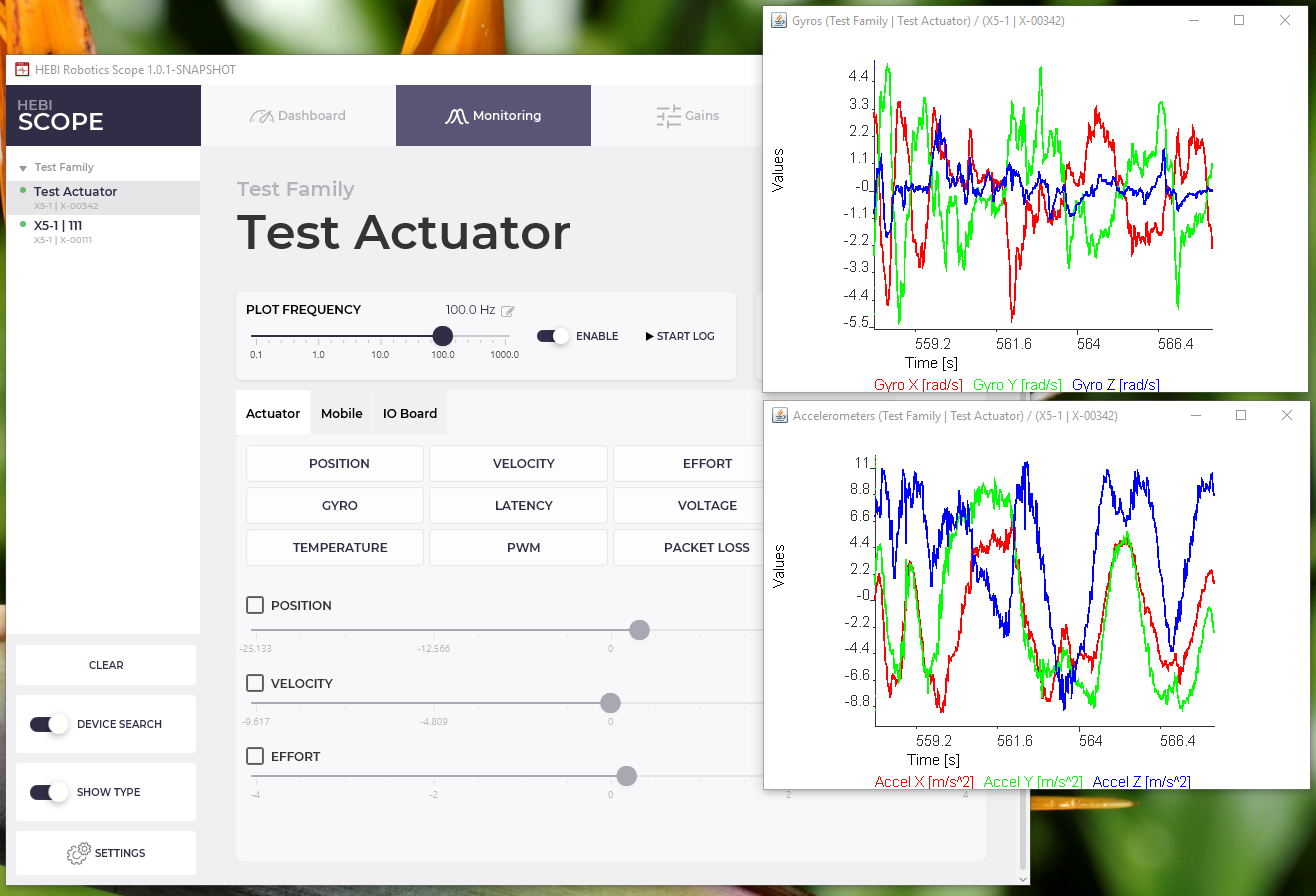
Gyro / Accelerometer
Every actuator has an internal 3-axis accelerometer and 3-axis gyro. Together these sensors are often called an inertial measurement unit (IMU).
The gyro measures the angular velocity of the actuator in radians / second. The accelerometer measures a combination of gravity and the actuator’s linear acceleration in meters / second2.
Current / Voltage
Each actuator senses its bus voltage, reported in units of volts, It also senses the current draw of the motor at the bus voltage, and the winding current through the windings of motor, both reported in units of amps.
Temperature
Each actuator reports back an ambient temperature, which is the temperature of the electronics in the actuator. Acuators also report back a modeled winding temperature, bulk actuator temperature, and motor sensor temperature, all in degrees Celcius.
| The winding temperature in particular informs a safety controller where motor power may be limited if it is too high. Watching the plot of winding temperature (the red line in the Scope GUI) is good indication of where you are running withing the actuator’s performance envelope. |
Next Steps
After becoming familiar with the basic functions of an actuator, there are multiple ways to control the actuators and configure their behavior.
Scope GUI
The Scope GUI provides a much wider range of capabilities for configuring, controlling, and testing out actuators than what is covered above. It is a good starting point for learning about actuation and control in general, and it is an important tool for debugging during devlopment.
Troubleshooting
Connection Issues
If Scope or the API are not showing any devices, it typically means that something is not set up correctly on the network. The most common reasons and fixes are below:
-
The device has a static IP address
-
Indicator: The Status LED immediately turns to a green fade after starting up (it never blinks green-orange after powering on).
-
Fix (Reset to DHCP): Follow procedures to reset the module to DHCP and restart. If you have access to a router or open network, this method is preferred.
-
Fix (Set to Static IP Address): If you do not have access to a network with DHCP, you can set the module to a known static IP address,
10.11.12.13with subnet mask255.255.255.0, and restart. Note that this method requires you to manually configure some network settings on your computer.
-
-
The device is not getting an address
-
Indicator: The Status LED blinks green-orange forever and never turns to a green fade.
-
Fix: Restart the module and wait at least 30 seconds (some routers can take a while to assigning IP addresses a new device, and then subsequent connections are faster). If the LEDs still do not turn to a green fade, it is likely that the Ethernet cables are not attached correctly or that the DHCP server /router is not accepting new devices (this can happen on corporate / institutional networks that have various security settings).
-
-
Scope or the API started before plugging in the network cable or adapter
-
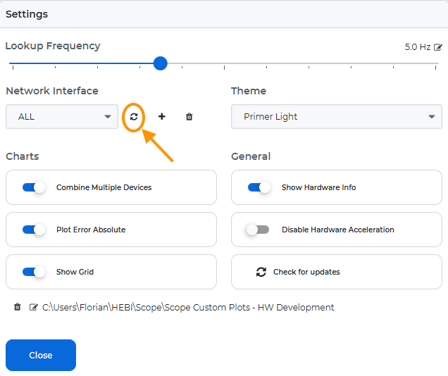
Scope and APIs search on all interfaces that were found on startup. If you change the network settings later on, you will need to restart the network search.
-
In Scope, click the refresh button under Network Interface in Settings. You can view all the current network interfaces with the dropdown menu.
-
-
-
In the various APIs, there are
reset()orinitialize()functions to refresh the network interfaces. There are alsolookup()functions that return the discovered network interfaces. The usage details depend on the specific API you are using.
FAQ
General
Do the HEBI APIs support real time control?
Yes. Each HEBI module run a real time operating system (RTOS) in the module itself that process commands and feedback at 1 kHz. This allows the APIs to provide a much more flexible soft-real time control from a computer over a standard Ethernet network. Under normal conditions on a wired LAN a module will show no packet loss, and round-trip latency of 1-2ms. Our APIs provide sub-millisecond synchronization of modules and API-level command/feedback rates of up to 1 kHz, although most applications only need to operate at about 100 Hz. More technical details can be found on our blog.
Other than a computer, what do I need to have to connect to a module?
The only other things you need are access to a wired ethernet network. There are no separate controllers / converters. Each module ships configured for DHCP so you will typically need a router that provides DHCP, at least to start.
How many modules can I have on a network?
The only limits are the same constraints of a standard ethernet network, which easily supports hundreds of modules. We have thoroughly benchmarked the performance of 40 of our modules running at 1 kHz (10x the usual update rate).
Do you have CAD models available for the actuators and accessories?
Yes, please go to cad.hebi.us. There you can find simplified CAD models of the actuators, and models most of our accessories.
API
Which API should I use?
It depends. It is probably best to start the with language you are most comfortable in. If you are just starting out in programming, the Python API or Matlab API are probably good choices. The full list of supported APIs can be found here.
Do you have a ROS API?
Yes. We provide both ROS 1 and ROS 2 APIs, although the ROS 1 API is legacy and no longer actively maintained. For more information, please see our ROS documentation.
Is there example / starter code for the various APIs?
Yes. We provide example code and tutorials on Github.
Scope
Can I run Scope in parallel with the APIs?
Absolutely. Scope is designed to run in conjunction with anything you may be doing from the API, from either the same or a different computer. The plotting tools in particular are an extremely useful tool for online configuring, tuning, and debugging.
T-Series Actuator
Are the actuators environmentally rated (dust/water protection, vibration)?
The T-Series actuators are meant primarily for indoor use, but has been improved since the days of the X-Series to provide better dust and water resistance (please still do not submerge the T-Series!). The primary dust/water ingress point is the connector end of the actuator.
What is the maximum temperature that a HEBI module can withstand?
The actuators can run at ambient temperatures up to 50º C. The actuator will have decreased performance at these temperatures, but it will not overheat or shut down. Above this temperature the electronics may shut down due to temperature limits. The internal temperature of the electronics is reported in the actuator feedback.
How hot do the housings of the actuator get?
The housing of an T-Series actuator can theoretically get to about 80 deg-C at near the motor if the module is stalled at full power for several minutes. In our testing here we have seen the housings of an T8 actuator get as high as 65 deg-C.
How fast (at what rate in Hz) can you command the actuators?
You can command up to 1kHz, although for our typical applications we control the actuators at around 100Hz. In general with a controlled wired network, the command and feedback rates are limited by the OS you are running. From macOS / Linux you can get reliable communication up to 1 kHz. On Windows you can get get reliable communication up to about 600 Hz.
What types of sensor feedback do actuators provide and, at what rate (in Hz) can you access this feedback?
All the sensors in the actuator can be accessed at up to 1kHz. These include typical feedback related to motion control like output position, velocity, torque, IMU, motor winding temperatures, voltage, current. We also provide a large amount of additional feedback like hardware timestamps, the status LED color, various internal temperatures, and internal motor velocity.
What is the actuator’s control bandwidth / roll-off frequency / frequency response?
The actuators have a roll-off frequency of about 5-30Hz, depending on the model of the actuator, the gains that set on the actuator, and the details of the commanded motion. Bode plots of the actuators under different load conditions are available in the hardware documentation.
What is the spring stiffness / compliance characteristics of the actuators?
The spring stiffness of the T-series actuators is non-linear and depends on the actuator type. Details are provided in the hardware documentation. The stiffness of each actuator is individually calibrated based on a non-linear curve fit.
What is the repeatability of the output motion of an individual actuator?
The repeatability of a single module is effected by the module’s load, speed, gains, etc. The actuator’s inherent backlash can be a factor when the output axis is unloaded, or when loads change direction. However, backlash has very little effect when the actuator is preloaded in one direction, for example, when it is holding up a load against gravity.
What does is mean when the LED blinks in (pattern)?
The status LED is used to indicate a variety of states about how it is being controlled and its internal state. Detailed information is provided in the status code table.
R-Series Actuator
Are the actuators environmentally rated (dust/water protection, vibration)?
The R-Series actuators are designed and tested to an IP67 rating. The primary dust/water ingress point is the connector end of the actuator. It is important to follow the instructions under the R-Series Quickstart guide about how to properly seal actuators.
Additionally, the actuators can be internally pressurized in order to achieve better underwater operation. Some notes about this use case are explained here.
What is the maximum temperature that a HEBI module can withstand?
The actuators can run at ambient temperatures up to 50º C. The actuator will have decreased performance at these temperatures, but it will not overheat or shut down. Above this temperature the internal motor may shut down due to temperature limits. The internal temperature of the electronics is reported in the actuator feedback.
How hot do the housings of the actuator get?
The housing of an R-Series actuator can theoretically get to about 80 deg-C at near the motor if the module is stalled at full power for several minutes. In our testing here we have seen the housings of an R8 actuator get as high as 65 deg-C. It helps that the R-Series Actuators are sealed so it is possible to cool these actuators down with splashes of water.
How fast (at what rate in Hz) can you command the actuators?
You can command up to 1kHz, although for our typical applications we control the actuators at around 100Hz. In general with a controlled wired network, the command and feedback rates are limited by the OS you are running. From macOS / Linux you can get reliable communication up to 1 kHz. On Windows you can get get reliable communication up to about 600 Hz.
What types of sensor feedback do actuators provide and, at what rate (in Hz) can you access this feedback?
All the sensors in the actuator can be accessed at up to 1kHz. These include typical feedback related to motion control like output position, velocity, torque, IMU, motor winding temperatures, voltage, current. We also provide a large amount of additional feedback like hardware timestamps, the status LED color, various internal temperatures, and internal motor velocity.
What is the actuator’s control bandwidth / roll-off frequency / frequency response?
The actuators have a roll-off frequency of about 5-30Hz, depending on the model of the actuator, the gains that set on the actuator, and the details of the commanded motion. Bode plots of the actuators under different load conditions are available in the hardware documentation.
What is the spring stiffness / compliance characteristics of the actuators?
The spring stiffness of the R-series actuators is non-linear and depends on the actuator type. Details are provided in the hardware documentation. The stiffness of each actuator is individually calibrated based on a non-linear curve fit.
What is the repeatability of the output motion of an individual actuator?
The repeatability of a single module is effected by the module’s load, speed, gains, etc. The actuator’s inherent backlash can be a factor when the output axis is unloaded, or when loads change direction. However, backlash has very little effect when the actuator is preloaded in one direction, for example, when it is holding up a load against gravity.
What does is mean when the LED blinks in (pattern)?
The status LED is used to indicate a variety of states about how it is being controlled and its internal state. Detailed information is provided in the status code table.
X-Series Actuator
Are the actuators environmentally rated (dust/water protection, vibration)?
The X-Series actuators are meant primarily for indoor use. The primary dust/water ingress points are the ethernet and power connectors on the modules. However some customers have used the X-Series actuators successfully outdoors, for example in an agricultural environment. In this situation the customer created their own 3D-printed housing to seal the power and ethernet connections on the side of the actuators.
What is the maximum temperature that a HEBI module can withstand?
The actuators can run at ambient temperatures up to 50º C. The actuator will have decreased performance at these temperatures, but it will not overheat or shut down. Above this temperature the electronics may shut down due to temperature limits. The internal temperature of the electronics is reported in the actuator feedback.
How hot do the housings of the actuator get?
The housing of an X-Series actuator can theoretically get to about 80 deg-C at near the motor if the module is stalled at full power for several minutes. In our testing here we have seen the housings of an X8 actuator get as high as 65 deg-C.
How fast (at what rate in Hz) can you command the actuators?
You can command up to 1kHz, although for our typical applications we control the actuators at around 100Hz. In general with a controlled wired network, the command and feedback rates are limited by the OS you are running. From macOS / Linux you can get reliable communication up to 1 kHz. On Windows you can get get reliable communication up to about 600 Hz.
What types of sensor feedback do actuators provide and, at what rate (in Hz) can you access this feedback?
All the sensors in the actuator can be accessed at up to 1kHz. These include typical feedback related to motion control like output position, velocity, torque, IMU, motor winding temperatures, voltage, current. We also provide a large amount of additional feedback like hardware timestamps, the status LED color, various internal temperatures, and internal motor velocity.
What is the actuator’s control bandwidth / roll-off frequency / frequency response?
The actuators have a roll-off frequency of about 5-30Hz, depending on the model of the actuator, the gains that set on the actuator, and the details of the commanded motion. Bode plots of the actuators under different load conditions are available in the hardware documentation.
What is the spring stiffness / compliance characteristics of the actuators?
The stiffness depends on the actuator and ranges from about 70 Nm/rad to about 170 Nm/rad. Details are provided in the hardware documentation. The stiffness in all the actuators is approximately linear.
What is the repeatability of the output motion of an individual actuator?
The repeatability of a single module is effected by the module’s load, speed, gains, etc. The actuator’s inherent backlash can be a factor when the output axis is unloaded, or when loads change direction. However, backlash has very little effect when the actuator is preloaded in one direction, for example, when it is holding up a load against gravity.
What does is mean when the LED blinks in (pattern)?
The status LED is used to indicate a variety of states about how it is being controlled and its internal state. Detailed information is provided in the status code table.
Kits
Is there example/starter code for the kits?
Yes. We provide example code for the various kits on Github.
When is a shunt regulator needed?
A shunt regulator is a good idea if you are powering off of a standard DC power supply and you expect a system to absorb large amounts of energy. For example, an arm moving a fairly heavy payload would need to absorb a lot of energy if it speeds the load up to a high velocity and then decelerates quickly. Some battery-powered systems may not need a shunt regulator.
What is the accuracy/repeatability of various arms?
Repeatability and accuracy of an arm will depend on the exact configuration, payload, and controller tuning. For the typical tasks we’ve tested we see repeatability of around +/- 2-3 millimeters and accuracy of around +/- 1-2 centimeters.
Shorter arms and arms with fewer DoF will tend to have better accuracy and repeatability. Arms and systems where that are tuned more for compliance and ‘soft’ interaction with the world will tend to be less repeatable than one that is tuned to be more ‘stiff’ for good position control.